Do you have a question about the Technics SU-V98 and is the answer not in the manual?
Details on output power, harmonic distortion, frequency response, input sensitivity, and S/N ratios.
Information on power consumption, power supply, dimensions, and weight.
Procedure for testing insulation resistance to prevent electric shock hazards.
Steps to take before and after repair, including voltage discharge and current checks.
Explanation of the protection circuit's function and troubleshooting steps when it activates.
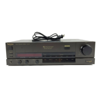
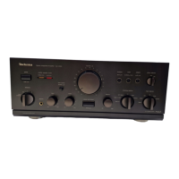
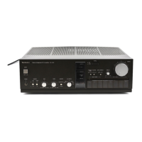
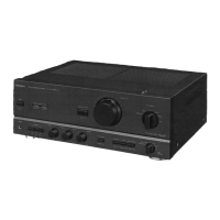
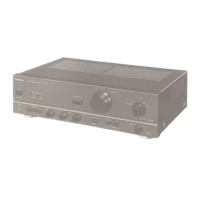
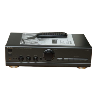
Description of front panel controls like power switch, input selector, volume, and tone controls.
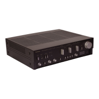
Details on rear panel terminals for speakers, AC outlets, and input/output connections.
List of accessories provided with the unit, including cables and remote control.
Illustrations showing how to connect the amplifier with CD players, equalizers, and processors.
Details on various terminals like GND, Tape, VCR, Pre Out/Main In, and their functions.
Overview of buttons on the remote control for power, CD, VCR, tuner, and amplifier functions.
Overview of buttons on the EUR64752 remote for CD, VCR, EQ, tuner, and amplifier functions.
Step-by-step guide to removing the unit's outer cabinet and front panel.
Instructions for accessing PCBs like volume, power switch, rear panel, and main PCB.
Steps to remove the power IC and regulator transistor from the circuit board.
Procedure for removing the cooling fan motor from its casing.
Details on remote control operation, buttons, and transmitted data codes.
Schematics for input selector, tone, super bass, volume, and motor drive circuits.
Schematics for the main power amplifier and power source circuits.
Schematics for the main circuit board and microcomputer/FL drive PCB.
Diagrams for volume control, speaker switch, and AC terminal PCBs.
Diagrams and pinouts for transistors, diodes, and ICs used in the unit.
Important safety instructions regarding fuse replacement to prevent fire hazards.
Overview of the main functional blocks, including equalizer, input selector, tone, and power amplifier circuits.
Exploded diagram showing the assembly of the unit's cabinet and external parts.
Exploded diagram showing the assembly of the remote control unit.
Lists of replacement integrated circuits, transistors, diodes, resistors, and capacitors.
Lists of cabinet parts, remote control parts, and mechanism parts.
Lists of variable resistors, coils, transformers, fuses, switches, relays, and other parts.
Explanation of the numbering system used for resistors.
Explanation of the numbering system used for capacitors.
Detailed list of resistors with their part numbers, values, and tolerances.
Detailed list of capacitors with their part numbers, values, and voltage ratings.
List of packing materials included with the unit.
List of specific accessories such as remote control cords, batteries, and headphones.
| Damping factor | 60 |
|---|---|
| Speaker load impedance | 4Ω to 16Ω |
| Input sensitivity | 2.5mV (MM), 150mV (line) |
| Signal to noise ratio | 100dB (line) |
| Channel separation | 55dB (line) |