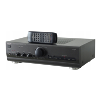
Do you have a question about the Technics SU-V620 and is the answer not in the manual?
Details the signal flow and control logic for unit operation.
Illustrates the circuit responsible for audio volume control.
Diagram of the audio tone control and amplification stage.
Circuit diagram for the headphone output and jack.
Comprehensive schematic of the primary audio processing and amplification circuits.
Diagram detailing the internal power supply and voltage regulation.
Schematic showing the power transformer and its connections.
Circuit diagram for AC power input and filtering, specific to GC area.
Wiring diagram for the Power Supply Printed Circuit Board.
Wiring diagram for the Power Transformer Printed Circuit Board.
Wiring diagram for the Main Printed Circuit Board.
Wiring diagram for the Tone Amplifier Printed Circuit Board.
Wiring diagram for the Operation Printed Circuit Board.
Wiring diagram for the Volume Printed Circuit Board.
Wiring diagram for the Headphones Jack Printed Circuit Board.
Functional block for the phono pre-amplifier stage.
Block diagram of the input signal selection circuitry.
Functional block representing the audio tone control amplifier.
Block diagram of the central microcomputer control unit.
Functional block for the main audio power amplification stage.
Overview of power supply, regulators, and transformer blocks.
List of all integrated circuits used in the unit.
List of all transistors used in the unit.
List of all diodes used in the unit.
List of all potentiometers and variable resistors.
List of all transformers, including power transformers.
Identification and location of physical cabinet components.
List and identification of packing materials used for the unit.
| Damping Factor | 60 |
|---|---|
| Input Sensitivity | 2.5mV (MM) |
| Channel Separation | 55 dB (1 kHz) |
| Speaker Load Impedance | 4Ω-16Ω |
| Dimensions | 430 x 139 x 344 mm |