EasyManua.ls Logo

Technics SU-V460 Service Manual

Technics SU-V460
35 pages
To Next Page IconTo Next Page
Page #1 background imageLoading...
Page #1 background image
www.freeservicemanuals.info
3/21/15
Digitized in Heiloo, Holland.
Question and Answer IconNeed help?

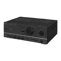
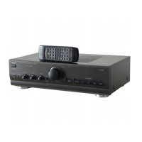
Do you have a question about the Technics SU-V460 and is the answer not in the manual?

Technics SU-V460 Specifications

General IconGeneral
Power Output60W per channel (8Ω, 20Hz-20kHz, 0.02% THD)
Damping Factor60 (8 ohms, 1 kHz)
Input Sensitivity2.5mV (MM), 150mV (line)
Speaker Load Impedance4Ω-16Ω
Dimensions430 x 150 x 370mm (W x H x D)
Channel Separation55dB (line)

Summary

Safety Warnings

General Safety Warning

General safety information and precautions for service technicians.

Traverse Deck Handling Precautions

Optical Pickup Static Handling

Procedures for handling the optical pickup to prevent static damage.

Electrostatic Discharge Prevention

Methods for grounding and preventing electrostatic discharge during repair.

Laser Diode Safety Precautions

Laser Diode Safety Guidelines

Warnings and precautions regarding the laser diode in the pickup unit.

Operation Checks and Component Replacement Overview

P.C.B. Checking Procedures

Steps for checking main and CD servo Printed Circuit Boards.

Main Component Replacement Procedures Overview

Overview of procedures for replacing major components and assemblies.

CD Servo P.C.B. Checking

CD Servo P.C.B. Checking Steps

Detailed steps for checking the CD servo Printed Circuit Board.

Traverse Deck Assembly Replacement

Traverse Deck Replacement Steps

Detailed steps for replacing the traverse deck assembly.

CD Servo P.C.B. Installation

CD Servo P.C.B. Installation Steps

Procedures for installing the CD servo P.C.B. into the traverse deck assembly.

Belt, Motor, and Switch Replacement

Belt and Motor Replacement Steps

Detailed steps for replacing the belt and loading motor assembly.

Power Supply Procedures

Power Supply to Unit Alone Method

Method for supplying power to the unit when operating independently.

Error Code Display and Servo Adjustment

Error Code Display Procedure

How to display and interpret error codes for fault diagnosis.

Servo Adjustment Procedure

How to perform servo adjustment and interpret results.

Troubleshooting Tables

Symptom and Cause Table (Table 1)

Table listing symptoms and probable causes for unit malfunctions.

Error Code Details (Table 2)

Detailed table of error codes, symptoms, causes, and signal values.

Troubleshooting Guide - CD Playback Issues

No CD Playback Diagnosis Flowchart

Flowchart for diagnosing issues when no CD playback occurs.

Optical Pickup Diagnosis Flowchart

Flowchart for diagnosing optical pickup related faults.

Troubleshooting Guide - Component Faults

IC702/IC703 Fault Diagnosis Flowchart

Flowchart for diagnosing faults related to IC702 and IC703.

Component Identification and System Wiring

Schematic Diagrams

CD Servo Circuit Details

Servo Processor and DSP Details

Circuit Schematics - System Control and Power

Block Diagrams - Servo and Motor Systems

Block Diagram - Servo Processor Functions

Block Diagrams - System Control and Power

Printed Circuit Board Layouts

Printed Circuit Board Layouts (Continued)

IC Pin Functions - System and Servo Amp

IC Pin Functions - Servo Processor

IC Pin Functions - Motor Drive and Continued

Loading Mechanism Parts Location

Related product manuals