Do you have a question about the Technics SU-V90D and is the answer not in the manual?
Covers main amp, digital section, and general specs like power, dimensions, and distortion.
Procedures for safe operation and initial checks before performing repairs.
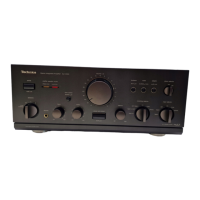
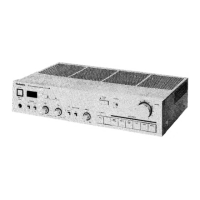
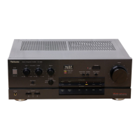
Identifies and describes the function of each control on the front panel of the amplifier.
Visual representation of the amplifier's internal signal flow and component connections.
Guides for connecting analog and digital audio sources to the unit.
Instructions for connecting speakers and the AC power cord.
Steps to remove the outer cabinet and the main printed circuit board.
Procedures for removing specific circuit boards like digital input and DAC.
Instructions for removing smaller PCBs, including input, speaker, and switch boards.
Procedures for removing PCBs related to headphones, tone, volume, and phono controls.
Steps to remove the main PCB and power transistors, with critical safety notes.
Schematics for digital input processing and digital-to-analog conversion stages.
Schematic diagrams illustrating the main audio amplification stages.
Essential safety guidelines for handling electronic components and avoiding static discharge.
Continuation of schematics for D/A conversion and audio amplification stages.
Schematics for phono EQ, input selector, and various switching functions.
Schematics for input/rec indicators and input/output terminal connections.
Schematics detailing volume control, tone amplification, and LED driver circuits.
Schematics covering power supply, voltage control, current drive, and protection systems.
Schematics for speaker terminals, headphone jacks, and power switch.
Reference charts detailing terminal pinouts for transistors, diodes, and ICs.
Layout diagrams for audio amplifier and power control/source PCBs.
Layouts for input selector and speaker terminal circuit boards.
Layouts for volume, tone, D/A converter, and phono selector PCBs.
Layouts for digital input terminal, switch, and indicator PCBs.
Layouts for headphone/speaker jack and power switch PCBs.
Comprehensive block diagram illustrating the signal flow and component interactions within the amplifier.
Diagrams illustrating connections for AC power, speakers, and headphones.
Diagrams showing wiring for audio inputs/outputs and digital signal connections.
Detailed pinout and function description for the digital interface IC (YM3623B).
Pinout and function details for digital filter (YM3404B) and converter ICs.
Procedures for adjusting idling currents in voltage and current drive amplifiers.
Steps for calibrating the DC offset of the D/A converter stages.
Diagrams showing adjustment VR and test point locations for calibration.
Exploded view illustrating the assembly and parts of the front panel.
Exploded view detailing the internal chassis structure and component layout.
List of external parts for the cabinet, chassis, and front panel.
Replacement part numbers for integrated circuits and transistors.
Replacement part numbers for diodes, basic components, and fuses.
Replacement part numbers for switches, coils, and transformers.
Guide for selecting resistors and capacitors by type, value, and tolerance.
List of included packaging materials and accessories.
Continuation of detailed part number listings for resistors and capacitors.
Final continuation of detailed part number listings for resistors and capacitors.