EasyManua.ls Logo

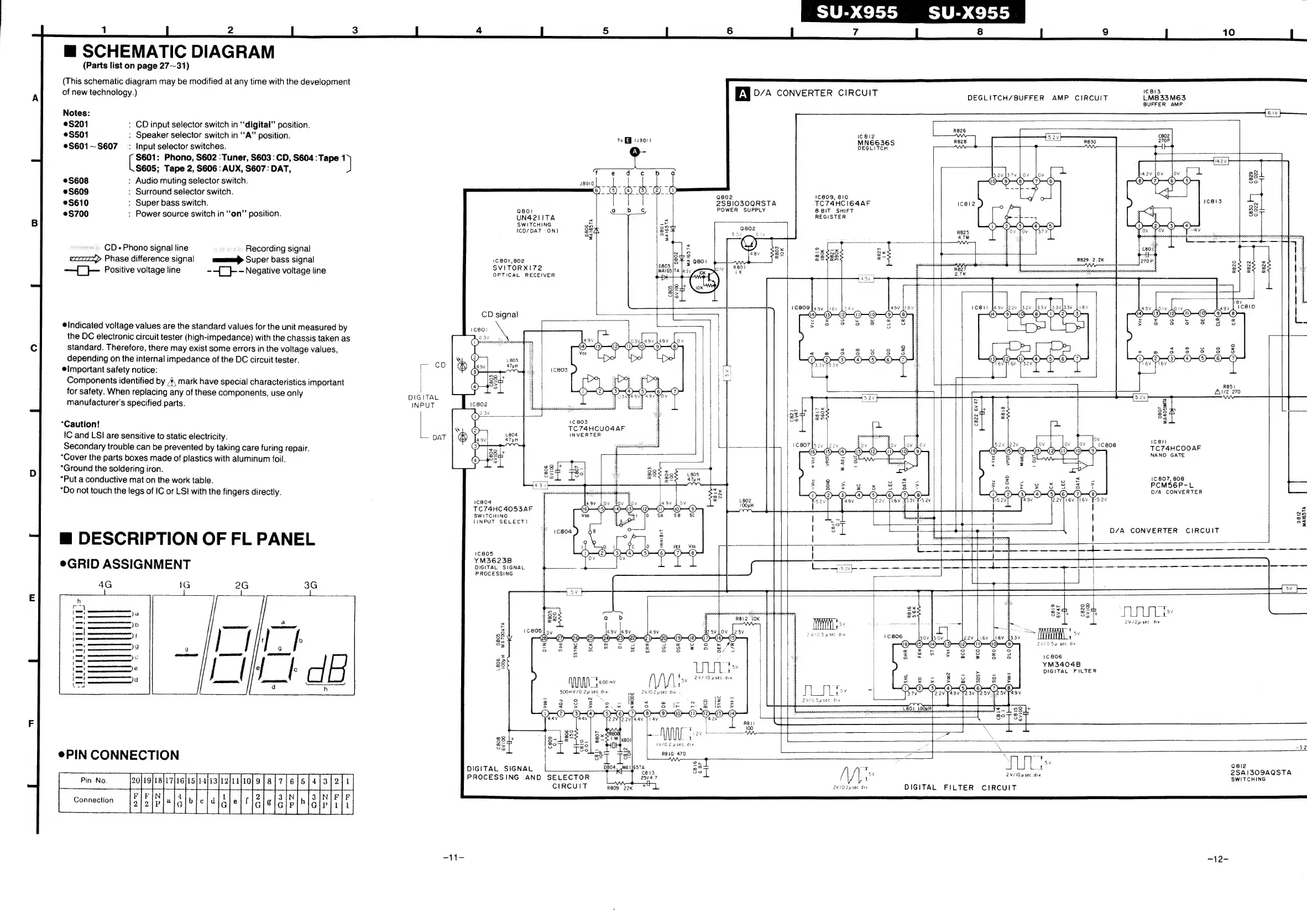
Technics SU-X955 - Schematic Diagram; Description of FL Panel; Pin Connection

Technics SU-X955
26 pages
Print Icon
To Next Page IconTo Next Page
To Previous Page IconTo Previous Page
Loading...
1
2
3
4
5
m@
SCHEMATIC
DIAGRAM
(Parts
list
on
page
27~31)
(This
schematic
diagram
may
be
modified
at
any
time
with
the
development
1
of
new
technology.)
A
D/A
CONVERTER
CIRCUIT
DEGLITCH/BUFFER
AMP
CIRCUIT
LMa33Me3
Notes:
S201
:
CD
input
selector
switch
in
‘digital’
position.
$501
:
Speaker
selector
switch
in
“A”
position.
to
veo
©S601~S607_
:
Input
selector
switches.
$601:
Phono,
S602
:
Tuner,
S603
:
CD,
S604
:
Tape
1
$605;
Tape
2,
S606
:
AUX,
S607:
DAT,
fed
er
gevbrv
Lov
©S608
:
Audio
muting
selector
switch.
S609
:
Surround
selector
switch.
@a08
aoe
16809
810
ae
eS610
:
Super
bass
switch.
sees
eSBlos0GRS
ees
S700
:
Power
source
switch
in
‘‘on”’
position.
UN4211TA
: 2
REGISTER
SWITCHING
won
so
{CD/DAT
:ON)
sch
Be
|
Sows
eee
I
8
8
ROR,
OREO
TS
lt
hectare
pete
aft
|
=
=
SSRI
«
CD
Phono
signal
line
:
ssa
Recording
signal
actin
a
Phase
difference
signal
mamma
Super
bass
signal
ag
a
se
ais
pon
hf
—
—}
Positive
voitage
line
--(_}--
Negative
voltage
line
Serica
RECCMER
CD
signal
Indicated
voltage
values
are
the
standard
values
for
the
unit
measured
by
the
DC
electronic
circuit
tester
(high-impedance)
with
the
chassis
taken
as
standard.
Therefore,
there
may
exist
some
errors
in
the
voltage
values,
depending
on
the
internal
impedance
of
the
DC
circuit
tester.
@Important
safety
notice:
Components
identified
by
4\
mark
have
special
characteristics
important
for
safety.
When
replacing
any
of
these
components,
use
only
R851
Al/2
270
bn
DIGITAL
=
§
manufacturer's
specified
parts.
INPUT
C802
ecctantnanpe
ss ae
eeetnatisennd
3
88
&
os
(C803
©
*Caution!
TC74HCUO4AF
re
:
io
NVERTER
IC
and
LSI
are
sensitive
to
static
electricity.
—
DAT
icell
TC7T4HCOOAF
NAND
GATE
Secondary
trouble
can
be
prevented
by
taking
care
furing
repair.
“Cover
the
parts
boxes
made
of
plastics
with
aluminum
foil.
*Ground
the
soldering
iron.
“Put
a
conductive
mat
on
the
work
table.
“Do
not
touch
the
legs
of
IC
or
LS!
with
the
fingers
directly.
ar
sacentnanetii
ate
aie:
ilk
1
1C
807,
808
PCMS6P-L
D/A
CONVERTER
TC74HC4053AF
SWITCHING
(INPUT
SELECT)
@
DESCRIPTION
OF
FL
PANEL
1C805
YM3623B
eGRID
ASSIGNMENT
DIGITAL
SIGNAL
1
On
8
x
=!
pei
lees
ase
Ssh
=
JULI»
;
:
2V/2p
sec.
div
<
|
t
as
'
5
C808!
3
VG
Spee
div
aes
ay
38
a
ov
@
©
eviGSpsec
a
Vv
I
9
:
8
eM
1806
—
os
as
YM3404B
a8
cf
ee
t
DIGITAL
FILTER
TF
600
mv
s
2W/OSpsec
div
:
355
Sey
#
Sy:
ae
i
a
1V/0.2
usec.
div
—
he
\
x32
Onde
9
woo
R810
470
=
XC
=
PIN
TION
ey]
:
;
ee
CONNESTIC
DIGITAL
SIGNAL
te
ae
sat
se
ionatae
25A|309AQSTA
PROCESSING
AND
SELECTOR
25v4.7
!
SWITCHING
eeoeee
TACRGRRRAR
CIRCUIT
Saat
av/o2usee
ti
DIGITAL
FILTER
CIRCUIT
7
i
aE
F
aie
-12-