EasyManuals Logo

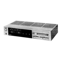
Technics SU-Z400 Service Manual

Technics SU-Z400
18 pages
To Next Page IconTo Next Page
To Previous Page IconTo Previous Page
Page #8 background imageLoading...
Page #8 background image
-}
U
Ey
4
Tele)
(R
ch)
(Playback)
Tape
2/ext—|
eh)
Speaker
impedance
switch
CD/video/aux
input
hee
and
Remote
162
4
Main
and
Remote
8Q
Main
or
Remote
8
~
162
Main
or
Remote
4
~
62
—__
Main
speaker
terminal
Phono
input
AC
inlet
(except
for
[XL]
)
Ground
Voltage
selector
+
(For
[XA]
and
[PC]
area
only)
peer
pus
(120V
<—©110V
—»220V
<—»240V)
(Rec
out
Tape
i
onus)
AC
outlets
(For
[XA]
and
[PC]
area
only)
(Playback)
bien
Remote
speaker
terminal
(R
ch)
@
The
power
supply
for
this
unit
varies
depending
upon
the
areas.
Also,
the
parts
used
for
power
supply
are
different.
So,
refer
to
the
circuit
diagram
and
the
replacement
parts
list.
*
220V
(50/60Hz)
for
continental
Europe.
(Except
for
United
Kingdom)
*
240V
(50/60Hz)
for
Australia
and
United
Kingdom.
*
110V/120V/220V/240V
(50/60Hz)
for
other
areas.
(For
other
areas
[XA
and
PC]
are
provided
with
voltage
selector
and
AC
outlets)
*
Phono
input
capacitance
is
about
150pF.
Mi
PROTECTION
CIRCUITRY
The
protection
circuitry
may
have
operated
if
either
of
the
If
this
occurs,
follow
the
procedure
outlines
below:
following
conditions
is
noticed:
1.
Turn
off
the
power.
@
No
sound
is
heard
when
the
power
is
turned
on.
2.
Determine
the
cause
of
the
problem
and
correct
it.
®
Sound
stops
during
a
performance.
3.
Turn
on
the
power
once
again
after
one
minute.
The
function
of
this
circuitry
is
to
prevent
circuitry
damage
if,
for
example,
the
positive
and
negative
speaker
connection
wires
are
‘‘shorted’’,
or
if
soeaker
systems
with
an
impedance
less
than
the
indicated
rated
impedance
of
this
unit
are
used.
Note
When
the
protection
circuitry
functions,
the
unit
will
not
operate
unless
the
power
is
first
turned
off
and
then
on
again.
Mi
BEFORE
REPAIR
AND
ADJUSTMENT
1.
Turn
off
the
power,
Discharge
both
power
supply
capacitors
(C904,
C905,
6800uUF)
through
a
10
ohm,
5W
resistor
to
ground.
Do
not
short
between
C904
and
C905.
It
may
damage
the
capacitors.
2.
After
completion
of
repair,
slowly
apply
the
primary
voltage
by
using
a
variac
to
avoid
over
current.
Current
con-
sumption
at
60Hz/50Hz
in
no
signal
mode
should
by
shown
below
with
respect
to
supply
voltage
110V/120V/
220V/
240V.
Power
supply
voltage
AC110V
AC120V
AC220V
AC240V
ae
mo
ey
115
~
225mA
[EK,
XL]
290
~
580mA
265
~530mA
145
~285mA
135
Seem
A
lother!
nm
as
aS
105
~
205mA
[EK,
XL]
60Hz
232
~464mA
212
~424mA
116
~228mA
108
~
212mA
[other]
Mi
SELECTING
THE
CORRECT
SPEAKER
IMPEDANCE
Consumed
current
1.
When
one
pair
of
speaker
systems
is
being
used,
connected
Note
that,
if
2
pairs
of
speaker
systems
are
used
at
the
same
to
the
MAIN
or
REMOTE
terminals,
set
the
speaker
time,
determine
the
composite
impedance
as
described
impedance
selector
to
the
range,
“4~6Q”
or
“8~162”,
which
below.
matches
the
impedance
of
the
speaker
systems
being
used.
R,XR,
Where:
2.
When
two
pairs
of
speaker
systems
are
being
used,
Ae
R,
+R,
R=total
impedance
Connected
to
the
MAIN
and
REMOTE
terminals:
R;=impedance
of
speaker
systems
1)If
the
impedance
of
both
systems
is
16
ohms,
set
the
connected
to
“MAIN”
terminals
speaker
impedance
selector
to
“16”.
R2=impedance
of
speaker
systems
2)
If
the
impedance
of
both
systems
is
8
ohms,
or
one
is
8
connected
to
“REMOTE”
terminals
ohms
and
the
other
is
16
ohms,
set
the
speaker
impedance
selector
to
“8Q”.
pa
drs

Questions and Answers:

Question and Answer IconNeed help?

Do you have a question about the Technics SU-Z400 and is the answer not in the manual?

Technics SU-Z400 Specifications

General IconGeneral
BrandTechnics
ModelSU-Z400
CategoryAmplifier
LanguageEnglish

Related product manuals