Do you have a question about the Technics SU-A600 and is the answer not in the manual?
Details on continuous power output for various frequencies and distortion levels.
Specifications for input sensitivity, signal-to-noise ratio, and impedance.
Information on the amplifier's frequency response and tone control capabilities.
Includes power supply, consumption, dimensions, and weight of the unit.
Steps for safely discharging power capacitors and performing initial voltage checks before repair.
Explains the conditions for protection circuit activation and the procedure to reset it.
Details on the AC power supply cords and plug adapters provided.
Critical safety information on AC mains lead wiring, fuse rating, and replacement.
Description of the power switch and operation indicators on the front panel.
Explanation of volume, balance, tape monitor, and input selector controls.
Details on tone controls, tone defeat button, and speaker selection buttons.
Information about the front panel headphone jack.
Guide for connecting turntables, ground wires, and tuners to the unit.
Instructions for connecting CD players and auxiliary audio sources.
How to connect tape decks and graphic equalizers to TAPE 1 and TAPE 2 terminals.
Methods for connecting main, second, and bi-wired speakers, including load impedance.
Instructions for setting the unit's power voltage and information on the cooling fan.
Step-by-step guide for removing the unit's outer cabinet and front panel assembly.
Procedure for removing the volume, operation, and tone amplifier circuit boards.
Steps for removing the power switch/headphones PCB and the rear panel.
Instructions for removing power transformer PCBs and the power supply PCB.
Steps for removing the main PCB, chassis base, and fan motor assembly.
Procedures for inspecting and analyzing the main printed circuit board for faults.
Detailed steps for safely removing and replacing the power IC, including compound grease application.
Diagrams illustrating the main amplifier circuit and the operation control circuit.
Schematics detailing the power supply circuit and voltage adjustment configurations.
Layout diagrams for the main, volume, and operation printed circuit boards.
Layout diagrams for tone, power switch, and power supply printed circuit boards.
Layout diagrams for the power transformer circuit boards.
Diagrams showing wiring for power transformers and the power supply unit.
Wiring diagrams for main circuits, input terminals, and output connections.
Wiring connections for control circuits, including power switch and headphone jacks.
Block diagram illustrating signal paths from input selection to amplifier stages.
Block diagram showing amplifier stages, muting, and control circuitry.
Block diagram detailing power supply, reset signal, and microcomputer control functions.
Detailed pinout and functional descriptions for the M37470M2215S microcomputer IC.
List of integrated circuits and transistors used in the amplifier, with part numbers and remarks.
List of diodes, variable resistors, and thermistors with specifications.
Part numbers and specifications for coils and power transformers.
List of cabinet parts including chassis, panels, knobs, and screws.
Details on packing cases, pads, and protective covers used for shipping.
List of accessories such as AC power supply cords, instruction manuals, and caution labels.
List of fuses, input/output jacks, and various switches with part numbers.
Part numbers for connectors, speaker terminals, earth terminals, and fuse holders.
List of relays, oscillators, and other miscellaneous components.
Exploded view illustrating the location of various cabinet and internal parts.
Diagrams showing the packaging configuration and identification of included parts.
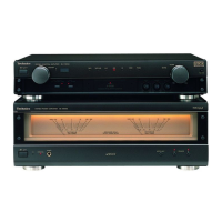
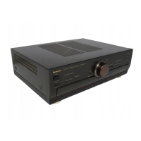
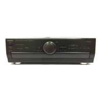
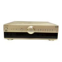
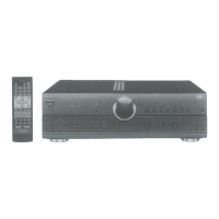
This document is a service manual for the Technics SU-A600 Stereo Integrated Amplifier, providing comprehensive information for its operation, maintenance, and repair.
The Technics SU-A600 is a stereo integrated amplifier designed to process and amplify audio signals from various sources before sending them to speakers or headphones. It features a range of input selectors, allowing users to connect multiple audio components such as a turntable (PHONO), CD player (CD), tuner (TUNER), auxiliary devices (AUX), and two tape decks (TAPE 1, TAPE 2). The amplifier includes a PHONO MM input with a specific capacitance for turntables, ensuring proper signal matching.
Audio processing capabilities include BASS and TREBLE tone controls, which can be engaged or bypassed using the TONE control button (ON/DEFEAT) to adjust the low and high-frequency sound ranges, respectively. A BALANCE control allows for adjustment of the left/right volume balance. The main VOLUME control regulates the overall output level.
The amplifier supports various speaker configurations. It can connect one pair of speakers to the "A" terminals, another pair to the "B" terminals, or both simultaneously. Additionally, it supports bi-wiring, where the treble and bass ranges of speakers are connected separately to the amplifier terminals using two speaker cords for enhanced sound nuance and detail, reducing band-range interference. A headphones jack (PHONES) is also provided for private listening.
Operation indicators (AMPLIFIER OPERATION MONITOR) provide visual feedback on the unit's status. The "VOLTAGE CONTROL" indicator illuminates when the unit is in normal operating condition, while the "CURRENT DRIVE" indicator lights up after a brief delay, signifying that the unit is ready for operation. These indicators also serve to alert users to abnormal conditions, such as DC voltage in the output or short-circuited speaker wires, which would trigger the protection circuitry.
The SU-A600 offers user-friendly controls for seamless audio experience. The "STANDBY/ON" switch allows for easy power management, switching the unit between active and standby modes. Input selectors are clearly marked for PHONO, TUNER, CD, AUX, TAPE 1, and TAPE 2, enabling quick switching between different audio sources. The TAPE MONITOR button allows users to monitor the sound being recorded from either TAPE 1 or TAPE 2, or to listen to the selected source.
Speaker selection is managed via dedicated buttons, allowing users to choose between "A" speakers, "B" speakers, or both. The amplifier's design accommodates various listening preferences and setups.
For models intended for specific regions (e.g., United Kingdom, Europe, Australia, and N.Z.), a voltage selector is provided to adjust the power voltage (110 V-127 V or 220 V-240 V) according to local requirements. This ensures compatibility and safe operation across different electrical standards.
The unit also includes a cooling fan that operates at high power output levels, ensuring optimal performance and preventing overheating during intensive use. However, it is noted that some countries may not have this feature.
The service manual provides detailed instructions for maintenance and repair, emphasizing safety precautions. Before any repair, users are instructed to turn off the power supply and discharge the voltage from power supply capacitors using a 10Ω, 10W resistor. After repairs, the primary voltage should be slowly applied using a power supply voltage controller to verify consumed current in NO SIGNAL mode.
The amplifier incorporates a protection circuitry designed to prevent damage from conditions like short-circuited speaker wires or speaker systems with impedance lower than the rated value. If the protection circuitry activates, the unit will not produce sound, and the "CURRENT DRIVE" indicator will not illuminate. Users are advised to switch off the power, identify and correct the problem, and then switch the power on again.
Disassembly instructions are provided with clear steps and diagrams for removing various components, including the cabinet, front panel assembly, volume P.C.B., operation P.C.B., tone amp P.C.B., power switch/headphones P.C.B., rear panel, power transformer P.C.B.s, power supply P.C.B., chassis base, and fan motor. Special attention is drawn to sharp edges on chassis components during disassembly and servicing.
Instructions for replacing the power IC are also detailed, including cutting joints, unsoldering pins, and applying compound grease between the heat sink and the power IC for proper heat radiation. The importance of tightening screws sufficiently after replacement is highlighted to ensure effective heat dissipation.
The manual also includes a comprehensive replacement parts list, with components identified by a "mark" having special characteristics important for safety, such as fire-retardant resistors, high-quality sound capacitors, and low-noise resistors. Users are advised to use only manufacturer-specified parts for replacement. Wiring connection diagrams, schematic diagrams, printed circuit board diagrams, a block diagram, and a function of IC terminals are provided to assist technicians in troubleshooting and repair.
| Input Sensitivity | 2.5mV (MM), 150mV (line) |
|---|---|
| Speaker Load Impedance | 4Ω to 16Ω |
| Type | Integrated Amplifier |
| Dimensions | 430 x 134 x 315 mm |
| Damping Factor | 60 (8 ohms) |