EasyManua.ls Logo

Technics SU-A700MK3

Technics SU-A700MK3
36 pages
To Next Page IconTo Next Page
Loading...
Question and Answer IconNeed help?

Do you have a question about the Technics SU-A700MK3 and is the answer not in the manual?

Technics SU-A700MK3 Specifications

General IconGeneral
BrandTechnics
ModelSU-A700MK3
CategoryAmplifier
LanguageEnglish

Summary

Specifications

Power Output Specifications

Describes various power ratings and conditions.

Distortion and Noise Levels

Details harmonic, intermodulation, hum, and S/N ratios.

Frequency Response and Tone Controls

Covers audio frequency range and EQ adjustments.

InputOutput and General Specs

Lists impedance, sensitivity, power consumption, dimensions.

Before Operation and Safety

Pre-Repair Safety Checks

Instructions for discharging capacitors and initial power-up tests.

Protection Circuitry Explained

Explains how the protection circuit works and how to reset it.

Included Accessories List

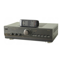
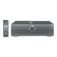
Lists the items supplied with the unit.

AC Mains Lead Safety Precautions

UK Plug and Fuse Replacement

Details safety for UK models, fuse type, and replacement procedure.

Mains Wiring Color Code

Explains wire colors for mains connection.

Connector Cover Removal

Instructions for removing the connector cover.

Front Panel Controls Overview

Power, Standby, and Indicators

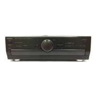
Describes power switch, standby, and operation indicators.

Volume and Source Selection

Details volume knob and source input buttons.

Tone, Balance, and Speaker Controls

Covers bass, treble, balance, tone defeat, and speaker selection.

Tape Monitor Function

Explains the tape monitoring feature.

Connecting Audio and Speaker Systems

Audio InputOutput Connections

Shows how to connect tuners, tape decks, CD players, etc.

Speaker Terminal Connections

Details connecting speakers to the unit.

Remote Control System Linkage

Explains connecting for remote control functions.

Speaker and Power Supply Connections

Speaker Cable Connection Guide

Step-by-step guide for speaker wire connection.

AC Power Cord Connection

Instructions for connecting the AC power cord.

Speaker Impedance Requirements

Recommended impedance for speaker connections.

Cooling Fan Operation Information

Information on the cooling fan.

Listening to Audio Sources

Power On and Speaker Setup

Steps to turn on the unit and select speakers.

Source Selection and Volume Control

How to choose audio sources and control volume.

Tape Monitor Usage Guide

How to use the tape monitor function.

Audio Adjustment and Headphone Use

Tone Quality Adjustment Controls

How to use bass, treble, and tone defeat controls.

Sound Balance Adjustment

Adjusting left/right sound balance.

Headphone Listening Procedure

How to use headphones and adjust volume.

Recording Audio Media

Recording from External Sources

How to record CDs, tuners, etc., to tape.

Tape-to-Tape Recording Procedures

Procedures for recording between tape decks.

Monitoring Recorded Sound

Checking sound during recording.

Troubleshooting Common Problems

Audio Output and Sound Quality Issues

Problems like no sound, lack of depth, reversed channels, hum.

Speaker and Protection Circuit Faults

Issues with one speaker, or sound stopping due to protection.

Internal Component Checks and Replacement

Printed Circuit Board (PCB) Checks

Overview of PCB checking procedures.

Main Component Replacement Overview

Introduction to replacing major parts.

PCB Removal and Access Procedures

Front Panel Assembly Removal

Steps to detach the front panel.

Tone and Volume PCB Removal

Instructions for removing specific PCBs.

Main PCB Inspection Procedure

Procedures for inspecting the main PCB.

Main PCB Access and Reconnection

Main PCB Detachment from Chassis

Steps to lift and remove the main PCB.

Front Panel Assembly Reconnection

Reconnecting the front panel to the main PCB.

Power IC Replacement Procedure

Pre-Replacement PCB Access Steps

Referencing previous steps for PCB access.

Power IC Removal and Installation

Steps for cutting joints, unsoldering, and installing the new IC.

Heat Sink Compound Application Caution

CAUTION regarding grease for heat dissipation.

Schematic Diagram Information

Component Identification and Safety Marks

Explains switch labels, safety marks, and special parts.

Static Electricity Handling Precautions

Cautions for handling ICs and LSIs.

Signal Line Type Definitions

Explains line types (voltage, signal).

Main Circuit Diagram Details

Phono EQ and Input Selector Circuits

Details of the phono pre-amp and input selector ICs.

REC OUT and Input Selector Logic

Schematic sections for recording outputs and selector IC.

Operation Circuit Diagram Details

Relay and Muting Control Circuits

Schematic for relay drivers and muting logic.

Microcomputer and LED Drive Circuits

Details of the microcomputer and LED indicators.

Volume and Tone Amp Circuit Diagrams

Volume Control and Motor Drive Circuits

Schematic for volume IC and motor drive.

Voltage Amplifier and Pre-Drive Stages

Details of the voltage amp IC and pre-drive transistors.

Tone Amplifier and Class AA Circuit Details

Tone Control and Amplifier Stages

Schematic for tone controls and amplifier stages.

Class AA Amplifier Bias Circuits

Details of the Class AA amplifier bias and current stabilizer circuits.

Power Amplifier and Relay Drive Diagrams

Power Amplifier IC and Protection Circuits

Schematic for the main power amplifier and protection features.

Relay Drive and LED Indicator Circuits

Details of relay control and LED driver circuits.

Headphone Jack and Motor Control Diagrams

Headphone Jack Circuitry Details

Schematic for the headphone output.

Fan Motor Control Circuit

Details of the fan motor control circuit.

Power Transformer and Supply Schematics

Schematics for transformer and power supply sections.

Main PCB Component Layout

Component Placement on Main PCB

Visual layout of components on the main PCB.

Tone Amplifier PCB Layout

Component Placement on Tone Amp PCB

Visual layout of components on the tone amp PCB.

Operation and Volume PCB Layouts

Operation PCB Component Placement

Visual layout of components on the operation PCB.

Volume PCB Component Placement

Visual layout of components on the volume PCB.

Headphone Jack PCB Component Placement

Visual layout of components on the headphone jack PCB.

Component Terminal Pinout Guides

IC, Transistor, and Diode Pin Assignments

Terminal guides for various integrated circuits, transistors, and diodes.

Wiring Connection Diagram Overview

Internal PCB Interconnection Schematics

Shows how PCBs are wired together.

Block Diagram of System Function

Signal Flow and Functional Blocks

Overall block diagram illustrating signal paths.

IC801 Microcomputer Terminal Functions

Microcomputer Terminal Descriptions

Detailed functions of IC801 terminals.

Replacement Parts List (ICs & Transistors)

Integrated Circuits (ICs) List

List of ICs, part numbers, and descriptions.

Transistors List

List of transistors, part numbers, and descriptions.

Replacement Parts List (Components & Connectors)

Components, Switches, and Connectors

List of various components, connectors, switches.

Cabinet Parts and Accessories List

Cabinet Components Identification

Part numbers for cabinet parts.

Included Accessories and Packing Materials

List of accessories, packing materials, grease.

Cabinet Parts Location - Top and Front

Top and Front Panel Assembly Layout

Visual guide for cabinet parts placement.

Cabinet Parts Location - Chassis

Chassis and Internal Component Layout

Visual guide for chassis and internal parts.

Resistors and Capacitors Identification

Resistor Part Number and Value List

Detailed list of resistors.

Capacitor Part Number and Value List

Detailed list of capacitors.

Capacitor Values and Specifications

Additional Capacitor Listings

Continuation of capacitor listings.

Product Packaging Details

Unit Packaging and Contents Layout

Diagram showing how the unit is packaged.

Related product manuals