EasyManua.ls Logo

Technics SU-A909 User Manual

Technics SU-A909
61 pages
To Next Page IconTo Next Page
Page #1 background imageLoading...
Page #1 background image
Table Of Contents
COVER
1 Note
2 Location of Controls
3 To Supply Power Source
3.1 Power Supply to Main
Circuit
3.2 Operation Check
4 Operation Checks and
Component
ReplacementProcedures
5 Type Illustration of ICs,
Transistors and Diodes
6 Schematic Diagram
6.1 Schematic Diagram
Notes
6.2 Schematic Diagram
7 Printed Circuit Board
Diagram
8 Block Diagram
9 Wiring Connection
Diagram
10 Measurements and
Adjustments
10.1 Measurement
instruments and Special tools
10.2 Output Voltage
Adjustment
11 Terminal Function of
ICs
11.1 IC701
(M38503M2404F) : Micro
Computer
12 Replacement Parts List
13 Cabinet Parts Location
14 Packaging
Service Manual
TOP NEXT
AD9907176C2
Control Amplifier
SU-C909U
Colour
(K)..........Black Type
Area
(E)..........Europe and Russia.
PV
PV
Question and Answer IconNeed help?

Do you have a question about the Technics SU-A909 and is the answer not in the manual?

Technics SU-A909 Specifications

General IconGeneral
Power Output100 W + 100 W (8 Ω)
Input Sensitivity2.5 mV (MM), 200 mV (line)
Speaker load impedance4 Ω - 16 Ω
Dimensions430 x 125 x 318 mm
Damping factor100
Channel separation70 dB (1 kHz)

Summary

Specifications (DIN 45 500)

Input/Output Specifications

Details input sensitivity, impedance, maximum input voltage, and output voltage.

Performance Characteristics

Specifies total harmonic distortion, signal-to-noise ratio, and frequency response.

Control and Muting Features

Outlines tone control ranges and muting attenuation.

Physical Specifications

Lists the unit's dimensions and weight.

Location of Controls

Front Panel Controls

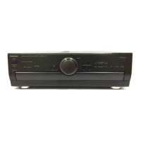
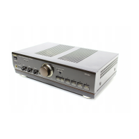
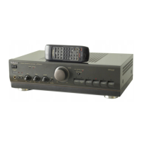
Identifies operational controls like Power, Input Selector, Volume, Tone, and Balance.

Front Panel Buttons and Indicators

Details buttons for panel access, tape monitoring, VGCA, and indicators for status and operation.

Remote Control Sensor

Locates the sensor for receiving remote control signals.

To Supply Power Source

Power Supply to Main Circuit

Explains how to supply power to the main circuit for testing and servicing.

Operation Check

Describes the procedure to verify the unit's operational status.

Operation Checks and Component Replacement/Procedures

Checking P.C.B. Operation

Details procedures for checking the operational status of main printed circuit boards.

Removing Each P.C.B.

Provides steps for safely removing printed circuit boards for component replacement.

Type Illustration of ICs, Transistors and Diodes

Schematic Diagram

Schematic Diagram Notes

Explains symbols, conventions, and notes related to the schematic diagrams.

Schematic Diagram

Presents the detailed circuit schematics for the unit.

Printed Circuit Board Diagram

Block Diagram

Wiring Connection Diagram

Measurements and Adjustments

Measurement Instruments and Special Tools

Lists the necessary test equipment and specialized tools for measurements and adjustments.

Output Voltage Adjustment

Provides step-by-step instructions for adjusting the output voltage.

Terminal Function of ICs

IC701 (M38503M2404F) : Micro Computer

Details the pin functions and specifications for the microcomputer IC701.

Replacement Parts List

Cabinet Parts Location

Packaging

Related product manuals