EasyManua.ls Logo

Technics SU-A80 User Manual

Technics SU-A80
25 pages
To Next Page IconTo Next Page
Page #1 background imageLoading...
Page #1 background image
Service
Manual
ORDER
NO.
HAD8606586A4
Stereo
DC
Control
Amplifier
SU-A80
Color
(K)...
Black
Type
(K)
|
[PA]....Far
East
PX.
(K)
|
[PE]....European
Military.
Please
use
this
manual
together
with
the
service
manual
for
Model
No.
SU-A6MK2,
Order
No.
HAD84062824C2.
SPECIFICATIONS
(IHF
°78)
@
AUDIO
SECTION
Frequency
response
PHONO
MM
20
Hz~20
kHz
RIAA
standard
curve
+0.2
dB
20
Hz~100
kHz
RIAA
standard
curve
+0.5
dB
TUNER,
CD,
VIDEO/AUX
1,
TV/AUX
2,
TAPE
1/EXT,
TAPE
2/VTR,
TAPE
3/DA
TAPE
/DA
PROCESSOR
20
Hz~20
kHz,
+0
dB,
—0.1
dB
0.5
Hz~200
kHz,
+0
dB,
-3
dB
Total
harmonic
distortion
(20
Hz~20
kHz)
PHONO
MM
0.002%
(0.5V
output
at
vol.
-30
dB)
0.002%
(3V
output
at
vol.
max.)
PHONO
MC
0.015%
(0.5V
output
at
vol.
-30
dB)
0.003%
(3V
output
at
vol.
max.)
TUNER,
CD,
VIDEO/AUX
1,
TV/AUX
2,
TAPE
1/EXT,
TAPE
2/VTR,
TAPE
3/DA
TAPE
/DA
PROCESSOR
0.002%
(0.5V
output
at
vol.
—30
dB)
0.002%
(3V
output
at
vol.
max.)
Input
sensitivity
PHONO
MM
0.63
mV
(2.5
mV,
IHF
’66)
MC
25
uV
(100
pV,
IHF
’66)
TUNER,
CD,
VIDEO/AUX
1,
TV/AUX
2,
TAPE
1/EXT,
TAPE
2/VTR,
TAPE
3/DA
TAPE
/DA
PROCESSOR
36
mV
(150
mV,
IHF
’66)
S/N
(IHF,
A)
PHONO
MM
80
dB
(90
dB,
IHF
’66)
MC
77
dB
(75
dB,
IHF
66)
TUNER,
CD,
VIDEO/AUX
1,
TV/AUX
2,
TAPE
1/EXT,
TAPE
2/VTR,
TAPE
3/DA
TAPE
/DA
PROCESSOR
97
dB
(106
dB,
IHF
’66)
Technics
Matsushita
Electric
Trading
Co.,
Ltd.
P.O.
Box
288,
Central
Osaka
Japan
Maximum
input
voltage
PHONO
MM
150
mV
(160
mV,
1
kHz)
Input
impedance
PHONO
MM
47
kilohms
MC
220
ohms
TUNER,
CD,
VIDEO/AUX
1,
TV/AUX
2,
TAPE
1/EXT,
TAPE
2/VTR,
TAPE
3/DA
TAPE
/DA
PROCESSOR
47
kilohms
Output
voltage
PRE
OUT
rated
2V
max.
8V
TAPE
1/EXT,
TAPE
2/VTR,
TAPE
3/DA
TAPE
/DA
PROCESSOR
(REC
OUT)
150
mV
Output
impedance
TAPE
1/EXT,
TAPE
2/VTR,
TAPE
3/DA
TAPE
/DA
PROCESSOR
(REC
OUT)
600
ohms
PRE
OUT
2
ohms
Turnover
frequency
BASS
500
Hz
SUPER
BASS
(12
dB/oct.)
78
Hz;
150.
Hz
TREBLE
2
kHz
SUPER
TREBLE
8
kHz
SUBSONIC
FILTER
(—12
dB/oct)
20
Hz
Shelving
tone
BASS
(50
Hz)
—5
dB~+5
dB
SUPER
BASS
(30
Hz)
0
dB~+10
dB
TREBLE
(20
kHz)
—5
dB~+5
dB
SUPER
TREBLE
(50
kHz)
—10
dB~+10
dB
Muting
—20
dB
H
VIDEO
SECTION
(VIDEO/AUX
1,
TV/AUX
2,
TAPE
2/VTR,
TAPE
3/DA
TAPE
/DA
PROCESSOR)
Output
voltage
(at
1V
input,
75
ohms
unbalanced)
1+0.1Vp-p
Maximum
input
voltage
1.5Vp-p
Input/output
impedance
75
ohms
unbalanced
Panasonic
Tokyo
Office
Matsushita
Electric
Trading
Co.,
Ltd.
6th
Floor,
World
Trade
Center
Bldg.,
No.
4-1,
Hamamatsu-cho
2-Chome,
Minato-ku,
Tokyo
105,
Japan
Question and Answer IconNeed help?

Do you have a question about the Technics SU-A80 and is the answer not in the manual?

Technics SU-A80 Specifications

General IconGeneral
Input Impedance47 kΩ
Damping factor100
Input sensitivity150mV (line)
Channel separation70 dB
Speaker load impedance4Ω to 16Ω
Power Output80W + 80W (8Ω, 20Hz - 20kHz, 0.02% THD)

Summary

Specifications

Audio Specifications

Detailed technical specifications for the audio performance of the amplifier.

Video Specifications

Technical specifications for the video input and output capabilities.

General Unit Information

Power and Dimensions

Details on power requirements, physical dimensions, and weight of the unit.

Service Notes and Changes

Important notes for service personnel and records of part changes.

Parts Lists and Diagrams

Cabinet and Chassis Parts

List of components related to the unit's housing and internal structure.

Screws, Washers, and Nuts

List of fasteners used in the assembly of the unit.

Packing Parts and Accessories

List of included accessories and packing materials.

Schematic Diagrams

Schematic Diagram with Revisions

Circuit diagram illustrating additions and deletions for specific revisions.

Disassembly Instructions

Cabinet and Front Panel Removal

Instructions for removing the outer cabinet and front panel.

Control Panel Door Removal

Procedure for detaching the control panel door and its associated parts.

Replacement Parts List

Component Replacement Details

Comprehensive list of replacement parts including integrated circuits, diodes, transistors, and transformers.

Exploded Views

Component Identification View

Visual representation of the unit's internal and external parts with reference numbers.

Safety Precautions

Insulation Resistance Test

Procedure for testing insulation resistance to ensure electrical safety after servicing.

Control Layout

Front Panel Controls Overview

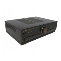
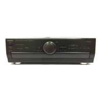
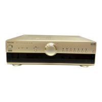
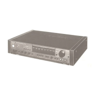
Description and location of all controls on the front panel of the amplifier.

Rear Panel Terminal Connections

Description and location of all input/output terminals on the rear panel.

Recording Procedures

Recording from Records and TV

Instructions for recording audio from vinyl records and TV broadcasts.

Disassembly Instructions

Bottom Board Removal Procedure

Instructions for removing the bottom board of the amplifier unit.

Printed Circuit Board Layouts

Main PCB Component Layout

Layout diagram for the main printed circuit board showing component placement.

Power Supply PCB Component Layout

Layout diagram for the power supply printed circuit board.

Wiring Diagrams

Video Signal Input Wiring

Wiring details for the video signal input selector printed circuit board.

Main Circuit Wiring Diagram

Wiring diagram for the main circuit board, showing connections between components.

Circuit Operation and Servicing

Input Selector Circuit Logic Explanation

Explanation of the flip-flop circuit logic used for input selection.

Equalizer Transistor Replacement Guide

Specific instructions for replacing equalizer differential transistors, including pair replacement.

Component Terminal Guides

Transistor and Diode Pinouts

Pinout configurations for various transistors and diodes used in the unit.

IC Terminal Information

Terminal information for integrated circuits.

Resistor and Capacitor Specifications

Resistor Specifications and Types

Detailed specifications and types for resistors used in the amplifier.

Capacitor Specifications and Types

Detailed specifications and types for capacitors used in the amplifier.

Comprehensive Parts List

Integrated Circuits, Diodes, and Transistors

List of replacement integrated circuits, diodes, and transistors with part numbers.

Variable Resistors and Other Components

List of replacement variable resistors and other electronic components with part numbers.

Mechanical Parts List

Cabinet, Chassis, and Fasteners

List of mechanical parts for the cabinet, chassis, and associated fasteners.

Packing Parts and Accessories List

List of packing materials and included accessories.

Exploded View - Front Section

Front Panel Assembly Exploded View

Exploded view focusing on the front panel assembly and related parts.

Exploded View - Rear and Internal

Rear Assembly and Internal Components Exploded View

Exploded view showing rear assembly and internal electronic components.

Related product manuals