EasyManuals Logo

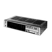
Technics SU-Z55 Service Manual

Technics SU-Z55
23 pages
To Next Page IconTo Next Page
To Previous Page IconTo Previous Page
Page #2 background imageLoading...
Page #2 background image
@
CONTENTS
Page
Page
SAFETY
PRECAUTIONS
........-..--2+2
eee
ee
2
PRINTED
CIRCUIT
BOARDS)
......
2.2.22
ee
eeee
7
BEFORE
REPAIR
AND
ADJUSTMENT
......-.-..4.-
2
POWER
AMPLIFIER
PROTECTION...........-..6.
10
LOCATION
OF
CONTROLS
........022
22
tee
eee
3
FLUORESCENT
LEVEL
METER
.........220005
10
PROTECTION
CIRCUITRY
........--2
020
eee
eee
3
BLOCK
DIAGRAM)...
wf
ee
ee
ee
11
DISASSEMBLY
INSTRUCTIONS
.........2+-2-055
4
SCHMATIC
DIAGRAM...
1...
ee
ee
ees
13
RESISTORS
&
CAPACITORS)
...
1...
ee
eee
ee
es
6
REPLACEMENT
PARTS
LIST
..........2020005
16
EXPLODED
VIEW
ww
Le
es
17
Wi
SAFETY
PRECAUTIONS
.
Before
servicing,
unplug
the
power
cord
to
prevent
an
electric
shock.
.
When
replacing
parts,
use
only
manufacturer’s
recommended
components
for
safety.
.
Check
the
condition
of
the
power
cord.
Replace
if
wear
or
damage
is
evident.
.
After
servicing,
be
sure
to
restore
the
lead
dress,
insulation
barriers,
insulation
papers,
shields,
etc.
.
Before
returning
the
serviced
equipment
to
the
customer,
be
sure
to
make
the
following
insulation
resistance
test
to
prevent
the
customer
from
being
exposed
to
a
shock
hazard.
OfhwWN
e
INSULATION RESISTANCE
TEST
1.
Unplug
the
power
cord
and
short
the
two
prongs
of
the
plug
with
a
jumper
wire.
2.
Turn
on
the
power
switch.
3.
Measure
the
resistance
value
with
ohmmeter
between
the
jumpered
AC
plug
and
each
exposed
metal
cabinet
part,
such
as
screwheads
antenna,
control
shafts,
handle
brackets,
etc.
Equipment
with
antenna
terminals
should
read
between
3MQ
and
5.2MQ
to
all
exposed
parts.
(Fig.
A)
Equipment
without
antenna
terminals
should
read
approximately
infinity
to
all
exposed
parts.
(Fig.
B)
Note:
Some
exposed
parts
may
be
isolated
from
the
chassis
by
design.
These
will
read
infinity.
Antenna
terminal
Exposed
Exposed
metal
metal
part
part
Ohmmeter
Ohmmeter
(Fig.
A)
(Fig.
B)
Resistance
=
3M2—5.2MQ
Resistance
=
Approx
oo
4.
If
the
measurement
is
outside
the
specified
limits,
there
is
a
possibility
of
a
shock
hazard.
The
equipment
should
be
repaired
and
rechecked
before
it
is
returned
to
the
customer.
lM
BEFORE
REPAIR
AND
ADJUSTMENT
1.
Turn
off
the
power
supply
and
short-circuit
of
power
supply
capacitors
(
C406,
6800HF
and
C407,
G800
HF)
at
resistance
(about
102,
5W)
in
order
to
discharge
the
charged
voltage.
Do
not
short
between
C406
and
C407
by
screwdriver.
It
may
damage
the
componet.
2.
Before
turning
on
the
power
supply
after
completion
of
repair,
slowly
apply
the
primary
voltage
by
using
a
power
supply
voltage
controller
to
make
sure
that
the
consumed
current
is
free
of
abnormality.
The
consumed
curremt
at
60Hz/50Hz
in
no
signal
mode
is
shown
below
with
respect
to
supply
voltage
110V/120V/220V/240V.
Power
supply
voltage
AC110V AC120V
AC220V
AC240V
200
~
400mA
180
~
355mA
100
~
200mA
90
~
180m
Cousumed
current
185
~
370mA
160
~
320mA
95
~
190mA
85
~
165m

Questions and Answers:

Question and Answer IconNeed help?

Do you have a question about the Technics SU-Z55 and is the answer not in the manual?

Technics SU-Z55 Specifications

General IconGeneral
BrandTechnics
ModelSU-Z55
CategoryAmplifier
LanguageEnglish

Related product manuals