PCB TEST MODE Procedure
MAIN
Wave ROM check
MAIN: IC106
1. Press and hold the two E keys shown below, and then turn on the power switch.
2. Select the GROUND sound.(SINE WAVE TEST)
3. Reduce the MAIN VOLUME level low enough.
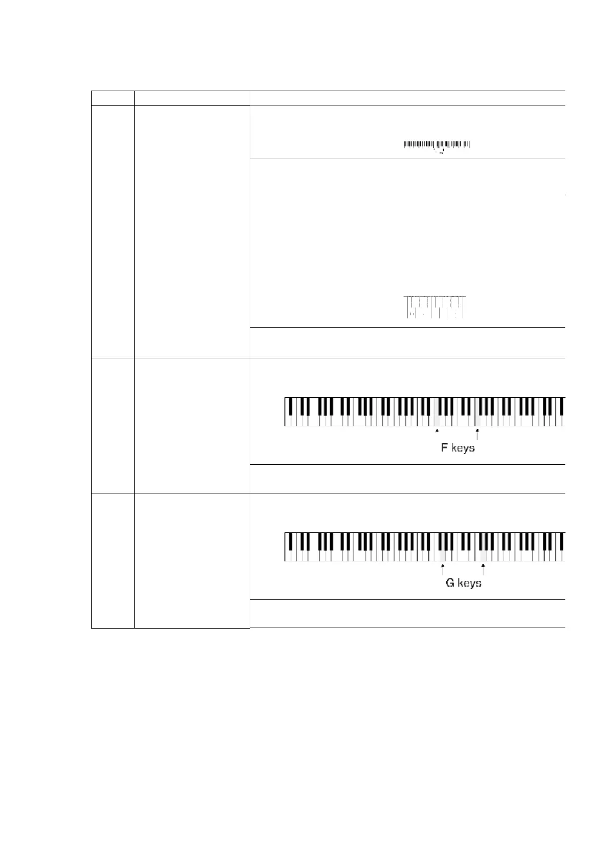
When set to the self-diagnostic mode, the Wave ROM outputs a
The Wave ROM correspond to the keyboard keys as shown in
When a key is pressed, the corresponding sine wave sound is
no sound is produced, or if the sound is distorted, the Wave
corresponding to that key is defective.
Select UPRIGHT sound.(OUTSEL TEST)
This method allows to diagnose also the output routes (L/R)
Wave ROM.
-
Select ELECTRIC / MODERN / MALLET & ORCH PERC sound.
You can test HIGH / LOW / 10dB down sound.
CPL
CPR
Control Panel buttons
LED lighting check
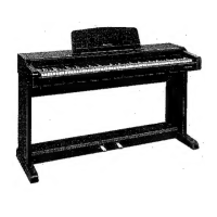
Press and hold the two F keys shown below, and then turn on
switch.
Press the buttons on the control and confirm that the
light.
LCD
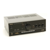
LCD check Press and hold the two G keys shown below, and then turn on
switch.
When set to the self-diagnostic mode, the test pattern is shown
display. Monitor the display to confirm that the characters
8. PRECAUTIONS BEFORE SERVICING
8.1. Precautions for measuring of the output waveforms
1. The waveform was measured with a “National Digital Storage
Oscilloscope VP-5730A”. Therefore the waveforms of musical
tone signals shown may differ somewhat due to the difference in
the timing of triggering.