Do you have a question about the Technics SX-PX201 and is the answer not in the manual?
Essential safety guidelines for servicing and handling electrical equipment.
Procedure for performing insulation resistance tests for user safety.
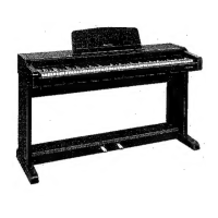
Step-by-step instructions for assembling the piano unit and stand.
Diagram and notation showing the full range of the piano keyboard.
How to reset the piano to its original factory settings and clear misoperations.
Overview of the arrangement and controls on the piano's control panel.
Explanation of key functions like DEMO, MODE SET, TRANSPOSE, SOUND, etc.
Details on LINE OUT, AUX IN, and MIDI terminals for connectivity.
Information on headphone jacks and pedal input connection.
Diagram showing the location of key components like PCBs and speakers.
Steps for removing the top cover and control panel.
Instructions for removing the CP P.C.B. and control panel ornament.
Procedures for removing the keyboard assembly and individual keys.
Common symptoms of trouble and their corresponding remedies.
Introduction to the self-diagnostic capabilities for component verification.
Procedure to check RAM (IC4) and ROM (IC3) using a checking device.
Tests for V53 Gate Array (IC2) and Control Panel LEDs.
Procedures for testing Wave ROM (IC7) and Keyboard ROM (IC2).
Details on MIDI functions, transmitted and recognized messages.
Important notes on measuring output waveforms and safety.
Identification of symbolic marks for resistors and capacitors.
Schematic showing the overall wiring connections between components.
Block diagram illustrating the main circuit's functional blocks.
Block diagrams for control panel and jack circuits.
Layout of components on the main P.C. board (component side).
Layout of traces on the main P.C. board (foil side).
Conditions for checking points and sample oscilloscope waveforms.
Schematic details of Digital Signal Processor and RAM connections.
Schematic details of tone generator and DC power supply circuits.
Component layout for the AS P.C. board.
Component layout for the ACP P.C. board.
Layout of the ACP P.C. board with measuring conditions.
Layout of the HP P.C. board with measuring conditions.
Schematic of the AC power supply, transformer, and rectifier circuits.
Schematic of headphone amplifier and power amplifier circuits.
Schematic diagram for the Control Panel (CP) P.C. board.
Schematic diagram for the Pedal Keyboard (PKB) P.C. board.
Component layout on the Control Panel (CP) P.C. board.
Component layout on the Pedal Keyboard (PKB) P.C. board.
Component layout for the Manual Keyboard 1 (MKB1) P.C. board.
Component layout for the Manual Keyboard 2 (MKB2) P.C. board.
Schematic diagram for the various jack connections (PEDAL, MIDI, AUX, LINE OUT).
Component layout on the Jack P.C. board.
List of replacement parts for PCBs, Oscillators, and Main P.C. Board components.
List of replacement parts for amplifier, headphone, jack, and pedal circuits.
List of replacement parts for control panel and manual keyboard circuits.
Diagram showing the location of parts within the main cabinet.
Diagrams showing components for the manual keyboard and stand.
List of replacement parts for switches, speakers, and transformers.
Detailed list of cabinet parts like music racks, keycovers, and knobs.
List of replacement parts for the stand assembly, including crossboard and legs.
List of replacement parts for manual keyboard keys, hammers, and springs.
List of various screws, washers, nuts, and PCB holders.
List of felt, rubber switches, chassis, and angle parts.
Diagram showing all parts included in the packing material.
List of packing parts such as cardboard, protection sheets, and pads.
List of operating instruction manuals provided in different languages.
| Type | Digital Piano |
|---|---|
| Number of Keys | 88 |
| USB | No |
| Tones | Piano, Electric Piano, Organ, Strings |
| Effects | Reverb, Chorus |
| Recorder | 1-track |
| Pedals | Damper, Soft, Sostenuto |
| Speakers | 2 x 12 cm |
| MIDI | Yes |
| Key Action | Weighted Hammer Action |