CONTENTS
HOW
TO
ASSEMBLE
THE
PIANO
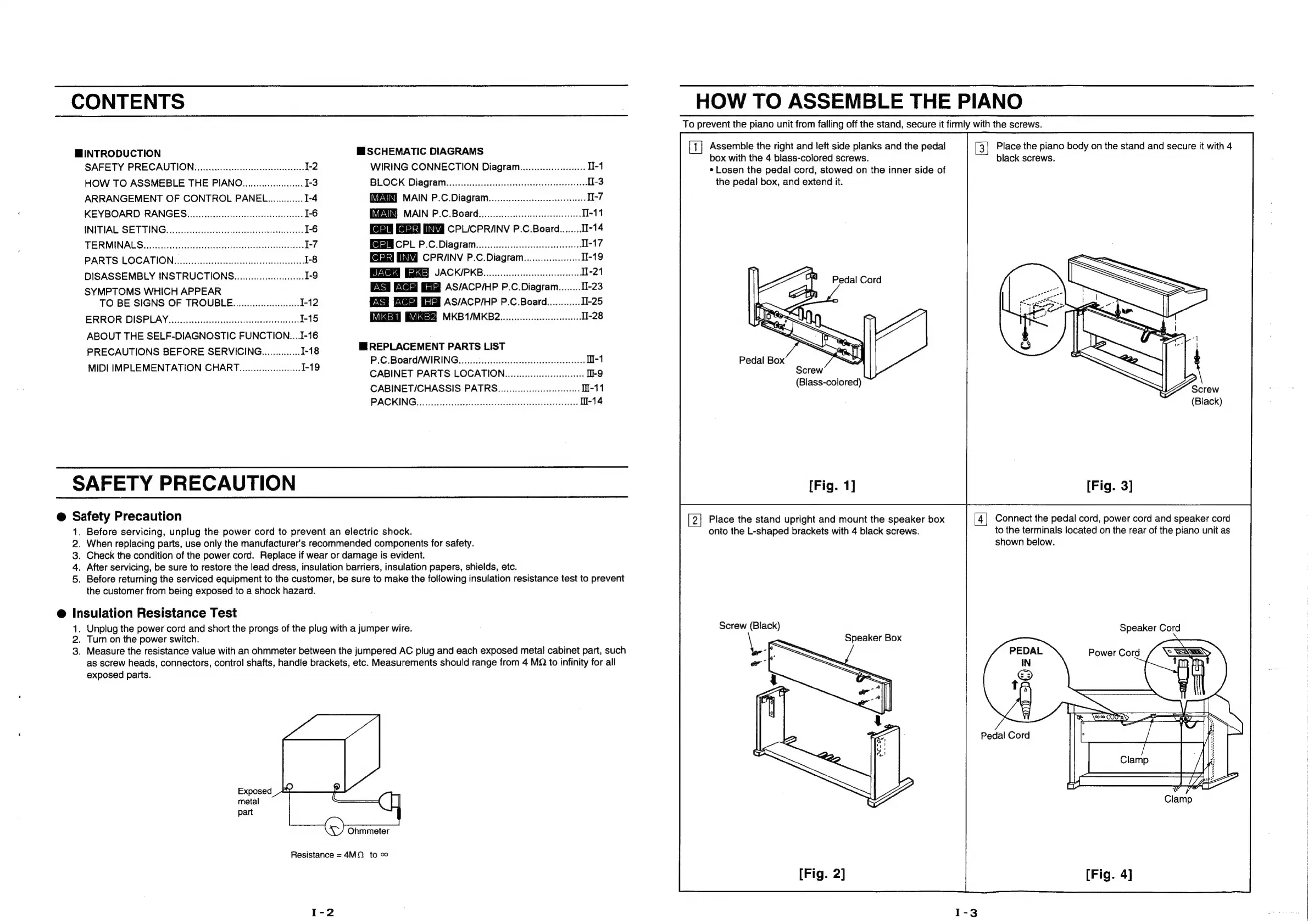
To
prevent
the
piano
unit
from
falling
off
the
stand,
secure
it
firmly
with
the
screws.
HINTRODUCTION
MESCHEMATIC
DIAGRAMS
|
eae
tee
tf
digest
Hala
and
the
pedal
[3]
oe
widely
body
on
the
stand
and
secure
it
with
4
SAFETY
PRECAUTION.
..............:::eccceesseeeteeeeeees
1-2
WIRING
CONNECTION
Diagram.............-.-:00
II-1
*
Losen
the
pedal
cord,
stowed
on
the
inner
side
of
HOW
TO
ASSMEBLE
THE
PIANO.................0008
1-3
BLOCK
Dia@graim.......ecccccccccccseeeeeeeeeeeeteeeeeeeeteas
TI-3
the
pedal
box,
and
extend
it.
ARRANGEMENT
OF
CONTROL
PANEL.)............
1-4
MAIN
P.C.Diagram................:cccceeeeeeeeerees
II-7
KEYBOARD
RANGEG...............:cccccececeeeeeeeeeeeeeees
1-6
MAIN
P.C.Board...............::escsesseeeeeeeeeees
I-11
INITIAL
SETTING.
0.00...
cccccsceeceeeeereeeaeerenees
I-6
CPL/CPRIINV
P.C.Board........
TI-14
TERMINALS
is
ec
cuss
cdscesieveswestesccceaescocpgeasecesenetaenders
I-7
Fee
CPL
P.C.
Diagram...
cee
cece
Tl-17
PARTS
LOCATION......scssssssssssssesssssesssesessseessunees
1-8
CPRANV
P.C.Diagram...........0.-:
I-19
DISASSEMBLY
INSTRUCTIONS.
........0:.:0csecce0
1-9
DACKIPRB
i.
iccdetidune
enone
H-21
SYMPTOMS
WHICH
APPEAR
AS/ACP/HP
P.C.Diagram........
I-23
TO
BE
SIGNS
OF
TROUBLE.............0....8.
I-12
AS/ACP/HP
P.C.Board............
I-25
ERROR
DISPLAY........cscssccsssssssessesssesssesseesseeeses
1-15
MKBAIMB2.,ssssiossscssastssnsesesies
I-28
ABOUT
THE
SELF-DIAGNOSTIC
FUNCTION....I-16
PRECAUTIONS
BEFORE
SERVICING...............
1-18
ee
ene
LIST
=
MIPRIMREEMENT
STON
CHART
aicaten
Ee
CABINET
PARTS
LOCATION..............::::eeceeeeeee
-9
CABINET/CHASSIS
PATRS.............:::ccccecseeeees
I-11
PACKING
scsccecsostitenstsstitedbagerseveaebesecceeteoaets
l-14
SAFETY
PRECAUTION
@
Safety
Precaution
Place
the
stand
upright
and
mount
the
speaker
box
Connect
the
pedal
cord,
power
cord
and
speaker
cord
1.
Before
servicing,
unplug
the
power
cord
to
prevent
an
electric
shock.
onto
the
L-shaped
brackets
with
4
black
screws.
to
the
terminals
located
on
the
rear
of
the
piano
unit
as
2.
When
replacing
parts,
use
only
the
manufacturer's
recommended
components
for
safety.
shown
below.
3.
Check
the
condition
of
the
power
cord.
Replace
if
wear
or
damage
is
evident.
4,
After
servicing,
be
sure
to
restore
the
lead
dress,
insulation
barriers,
insulation
papers,
shields,
etc.
5.
Before
returning
the
serviced
equipment
to
the
customer,
be
sure
to
make
the
following
insulation
resistance
test
to
prevent
the
customer
from
being
exposed
to
a
shock
hazard.
Insulation
Resistance
Test
1.
Unplug
the
power
cord
and
short
the
prongs
of
the
plug
with
a
jumper
wire.
Screw
(Black)
Speaker
Cord
2.
Turn
on
the
power
switch.
Speaker
Box
3.
Measure
the
resistance
value
with
an
ohmmeter
between
the
jumpered
AC
plug
and
each
exposed
metal
cabinet
part,
such
°
a
Power
Cord
as
screw
heads,
connectors,
control
shafts,
handle
brackets,
etc.
Measurements
should
range
from
4
MQ
to
infinity
for
all
—
exposed
parts.
[|
=
VE
ae,
SS
podaicors
fp
Exposed
metal
part
Ohmmeter
Resistance
=
4M.
to