18
6 Installation
6.1 Plates
The unit is supplied with warning and attention plates as listed in the relevant table.
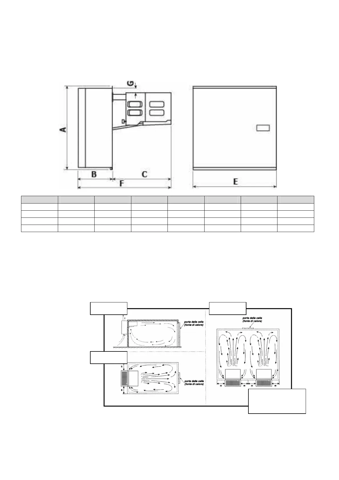
6.2 Dimensions
Mod. A B C D E F G
AT1 767 310 535 485 845 40
AT2 767 310 535 785 845 40
AT3 860 400 670 760 1070 50
AT4 860 450 670 760 1120 50
6.3 Location
To obtain optimal operation of the unit act as follows:
A) Place the unit in a well ventilated room, far from heat sources.
B) Limit the number of door openings.
C) Make sure that the unit has good air supply and discharge.
D) Fit a drain line to the defrost water drain connection in the lower part of the unit.
Note: GM units are equipped with automatic evaporation of defrost water; drain is just
a precaution in case of troubles.
6.4 Free room
When installing the unit leave enough free room to allow opening, correct use and easy maintenance in
safe conditions.
Solution 1 Solution 3
Solution 2
Installation in a
coldroom with