19
6.5 Installation
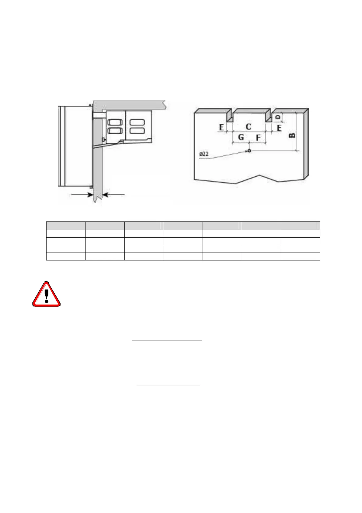
Straddle version:
Before mounting the unit prepare the cuts in the cold room wall as shown in the picture.
Fix the unit in place with the appropriate screws. Position the unit on the cold room, connect the evaporator
drain tray spigot and the hole prepared in the cold room wall using the supplied pipe with pre-inserted
heater (for low temperature units only). Fill the hole in the wall with insulating material, polyurethane or
silicone, and mount the hole cover.
Mod. B C D E F G
AT1 324 295 80 55 147,5 147,5
AT2 324 595 80 55 297,5 297,5
AT3 400 542 65 85 271 271
AT4 450 542 65 85 271 271
ATTENTION
Check that the unit and its devices have suffered no damages during transport. Pay
special attention to the components
secured to the electric panel door and to the refrigerating circuit pipes. Mount the unit
as shown in the drawings; make sure that the electric connections are carried out
properly.
6.6 Safety devices
The following
mechanical safety devices
are supplied:
1. Fixed upper and side protections for evaporator and condensing unit, secured
by locking screws.
2. External fan protections placed on the evaporating and condensing units,
secured with screws.
The following
electrical safety devices
are supplied:
a. Protection of fans (belonging to motors) against high power absorption;
with automatic reset.
b. High pressure switch (only for special components) to protect against excessive
pressure; with automatic reset.
Max 120