18
LCD control panel introduction
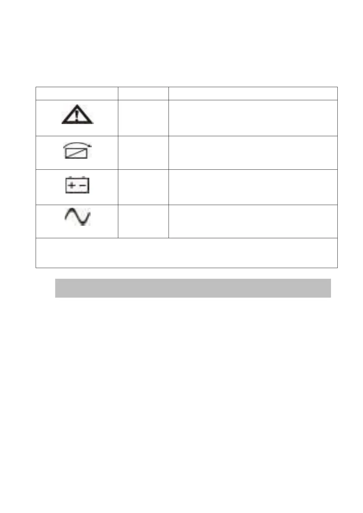
(1)LED(from top to bottom: “alarm”, “bypass”, “battery”, “inverter”);
(2)On-Line UPS LCD display;(3)Buttons-FUNC button/OFF button/On button.
The UPS has an active alarm or fault.
The UPS is in Bypass mode.
The UPS is operating normally on bypass
during High Efficiency operation.
The UPS is on Battery mode.
The UPS is operating normally on Oline.
NOTE
When power on or startup , these indicators will turn on and off sequentially.
NOTE
On different operation modes , these indicators will indicate differently.
2-7 Setup the UPS
Step 1: UPS input connection
Plug the UPS into a two-pole, three-wire, grounded receptacle only. Avoid using
extension cords.
For 208/220/230/240VAC models: The power cord is supplied in the UPS
package.
Step 2: UPS output connection
For socket-type outputs, simply connect devices to the outlets.
For terminal-type input or outputs, please follow below steps for the wiring
configuration:
a) Remove the small cover of the terminal block
b) Suggest using AWG14 or 2.1mm
2
power cords for 3KVA (220/230/240VAC
models).
c) Upon completion of the wiring configuration, please check whether the