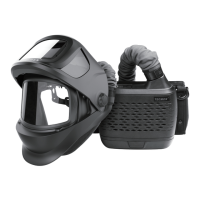
WELDING HELMET OPERATING INSTRUCTION
WARNING
Auto-Darkening welding helmets are designed to protect the eye and face from sparks,
spatter and harmful radiation under normal welding conditions. This auto darkening filter will
automatically turn on when pick it up. The filter automatically changes from a light state to a
dark state when an arc is struck, and it returns to the light state when welding stops.
The Auto-Darkening welding helmet comes assembled. But before it can be used, it
must be adjusted to fit the user properly. Check battery surfaces and contacts and
clean it if necessary. Verify if the battery is in good condition and installed properly.
Set up for delay time, sensitivity and shade number for your application.
The helmet should be stored in dry, cool and dark area and remove the battery, when
not using it for a long time.
WARNING
The user must stop using the auto-darkening welding helmet immediately
if the above-mentioned problems cannot be corrected. Contact the dealer.
• Irregular Darkening Dimming
Headband has been set unevenly and there is an uneven distance from the eyes to the filter
lens. (Reset the headband to reduce the difference to the filter).
• Auto-Darkening filter does not darken or flickers
① Front cover lens is soiled or damaged (Change the cover lens).
② Sensors are soiled (Clean the sensors surface).
③ Welding current is too low (Adjust the sensitivity level to higher).
④ Check battery and verify they are in good condition and installed properly. Also, check
battery surfaces and contacts and clean if necessary.
• Slow response
Operating temperature is too low (Do not use at temperatures below -5°C or 23°F).
• Poor vision
① Front/inside cover lens and/or the filter is soiled (Change lens).
② There is insufficient ambient light.
③ Shade number is incorrectly set (Reset the shade number).
④ Check if removing the film on the front cover lens.
• Welding helmet slips
Headband is not properly adjusted (Readjust the headband).
COMMON PROBLEMS AND REMEDIES
• VARIABLE SHADE CONTROL
After turn on the lens, short press “FUNC” button to choose “SHADE”, and adjust the lens
shade number. Use “ ” and “ ” buttons to select the lens shade in the dark state. The shade
range for each mode are as follows:
Cutting Mode − Shade 5 ~ 8 (See fig.15a) Weld Mode − Shade 9 ~ 13 (See fig.15b)
Grind Mode − No. 4 only (See fig.15c)
Select the proper shade number for your welding / cutting process, by referring to the “Shade
Guide Table” on page 19.
• SENSITIVITY CONTROL
Press “FUNC” button to choose “SENSITIVITY”. Use “ ” and “ ” buttons to make the lens
more or less sensitive to arc light of different welding processes. Sensitivity setting 5-10 is
the normal setting for everyday use. The sensitivity ranges for each mode are as follows:
Cutting Mode (Shade 5 ~ 8) / Weld Mode (Shade 9 ~ 13) − Sensitivity 0 ~ 10 (See fig.16a /
16b)
Grind Mode − No sensitivity adjustment
As a simple rule for optimum performance, it is recommended to set sensitivity to the
maximum at the beginning and then gradually reduce it, until the filter reacts only to the
welding light flash and without annoying spurious triggering due to ambient light conditions
(direct sun, intensive artificial light, neighbouring welder's arcs etc.).
It may be necessary to adjust helmet sensitivity to accommodate different lighting conditions
or if lens is flashing On and Off. Adjust helmet sensitivity as follows: Adjust helmet sensitivity
in lighting conditions helmet will be used in.
• Press “ ” button to lower setting to 0.
• Face the helmet in the direction of use, exposing it to the surrounding light conditions.
• Press “ ” button repeatedly until the lens darkens, then press “ ” button until lens clears.
Helmet is ready for use. Slight readjustment may be necessary for certain applications or if
lens is flashing on and off.
• DELAY CONTROL
Press “FUNC” button to choose “DELAY”, begin lens delay adjustments. Use the Lens Delay
Control “ ” and “ ” buttons to adjust the time for the lens to switch to the clear state after
welding or cutting.
Cutting Mode (Shade 5 ~ 8) / Weld Mode (Shade 9 ~ 13) − Delay 0 ~ 10 (See fig.17a / 17b)
Grind Mode − No sensitivity adjustment
The delay is particularly useful in eliminating bright after-rays present in higher amperage
applications where the molten puddle remains bright momentarily after welding. Use the
Lens Delay Control buttons to adjust delay from 0 to 10 (0.1 to 1.0 second). When welding
stopped, the viewing window automatically changes from dark back to light but with a
pre-set delay to compensate for any bright afterglow on the workpiece. The delay time /
response can be set from Level 0 to level 10. It is recommended to use a shorter delay
with spot welding applications and a longer delay with applications using higher currents.
Longer delays can also be used for low current TIG welding, and TIG / MIG / MAG pulse.
• ADJUSTING THE FIT OF THE HELMET
The overall circumference of the headband can be made larger or smaller by rotating the
knob on the back of the headband (See adjustment “Y” in fig.18). This can be done while
wearing the helmet and allows just the right tension to be set to keep the helmet firmly on
the head without it being too tight.
• If the headband is riding too high or too low on your head, adjust the strap which passes
over the top of your head. To do this release the end of the band by pushing the locking pin
out of the hole in the band. Slide the two portions of the band to a greater or lesser width
as required and push the locking pin through the nearest hole (See adjustment “W” in
fig.18).
• Front and back bands will automatically self-adjust according to headform, and soft pads
suit forehead and back of head perfectly, which will bring more comfort (See fig.19a). Test
the fit of the headband by lifting up and closing down the helmet a few times while wearing
it. If the headband moves while tilting, re-adjust it until it is stable.
• ADJUSTING THE DISTANCE BETWEEN THE HELMET AND THE FACE
Step 1: Press down and hold the “LOCK” latch on both sides (See fig.19b) and it can be
slide back and forth.
Step 2: Loosen the “LOCK” latch and keep it snap into slots. Please make sure the
distance between the lens to both eyes are equal, to avoid uneven darkness.
• ADJUSTING VIEW ANGLE POSITION
Tilt adjustment is located on right side of helmet. Loosen the right headgear tension knob
and adjust the lever forward or back to the proper position. Re-tighten the right headgear
tension knob (See fig.19c).
12
 Loading...