TECNOEKA Srl ________________________________________________________________use and instruction manual
page 6 ____________________________________________________________________________________________
Water drainage
Water drainageWater drainage
Water drainage
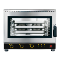
A drain pipe (see Fig. 1) comes out from the rear of the appliance, to drain the oven cavity. This
pipe must be connected up to a pipe made to resist steam temperatures (90°C-100°C) with an
internal diameter of 30 mm (DN 30). To prevent choking, it is best to use a rigid pipe and make
sure there are no "elbow" bends anywhere along the drain line.
Furthermore, the drain line must slope down (minimum slope 5%) along its full length (the
length in question is from the appliance's drain pipe to the drain point and must not exceed 2
metres). The drain line must run into an open floor drain (Fig.2). In addition, there must be a free
air gap of at least 25 mm (distance between the drain line coming from the appliance and the
funnel on the drain standpipe). Whatever the case, in order to comply with current hygiene
standards, the line connected to the appliance's drain pipe must not come into direct contact
with the drain point. It is advisable to include a suitable trap in the line connecting the appliance's
drain outlet to the grey water waste system, thus stopping the steam coming back out of the
drain.
F
FF
FIG.
IG. IG.
IG. 1
11
1
FIG.
FIG. FIG.
FIG. 2
22
2
Connecting the power cable
Connecting the power cableConnecting the power cable
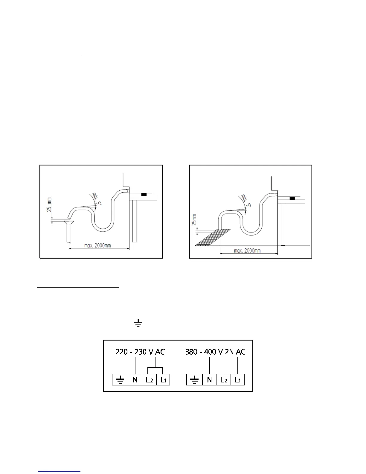
Connecting the power cable - To access the terminal board, just remove the appliance's rear side-
panel. Loosen the cable gripper and allow the cable to pass through it. Arrange the conductors
so that the earth conductor is the last to detach from its terminal if the cable goes into a state of
faulty traction. Connect the phase
phasephase
phase conductors to the terminals marked “L1”
“L1”“L1”
“L1” and “L2”
“L2”“L2”
“L2”,
connecting the neutral
neutral neutral
neutral conductor to the terminal marked "N"
"N""N"
"N" and the earth
earthearth
earth conductor to the
terminal marked with the symbol
according to the following lay-out:
(this electrical connection lay-out is located near the power supply terminal board ). Tighten the
cable gripper and re-fit the rear side-panel of the appliance.
The appliance must be connected to an equipotential system
equipotential systemequipotential system
equipotential system whose efficiency must first be
checked according to current legal regulations.