Do you have a question about the tecnoelettra AT206 and is the answer not in the manual?
Welcomes the customer and thanks them for purchasing the electric panel.
Provides essential guidelines for safe and correct use of the manual and equipment.
Explains the purpose of symbols used to highlight dangers and important information.
Offers user tips focused on safety and adherence to instructions and regulations.
Details hazardous situations and emphasizes safe installation and technical condition requirements.
States compliance with EEC Directive 86/594 regarding irrelevant sound pressure levels.
Defines symbols used to indicate different levels of danger for users.
Provides precautions for storing the electric panel to prevent damage before installation.
Instructs on how to transport the electric panel safely and inspect for transit damage.
Mentions that panel dimensions are shown on the 'Technical Data' identification plate.
Advises on disposing of the appliance according to legislative provisions and destroying identification plates.
Specifies that maintenance and service must be performed by authorized 'Specialized personnel'.
Recommends contacting the retailer or manufacturer for repairs and emphasizes using original spare parts.
Refers to a specific document (n.5159) for detailed guarantee conditions.
Lists required information for ordering spare parts, including serial number and component codes.
Describes what is included in the AT206 panel package, such as connectors, fuses, and manual.
Explains the technical plate's location and its role in certifying conformity with EEC directives.
Defines the meaning of each data field found on the panel's identification plate.
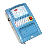
Illustrates the AT206 panel's external components and internal connections with labels.
Guides the user on initial panel setup, time programming, and pre-start checks.
Provides a step-by-step procedure for setting the current time on the AT206 panel.
Explains the meaning of various LEDs on the AT206 panel for status and alarms.
Describes the function of each button on the AT206 control panel.
Details the operational modes (Reset, Manual, Automatic) and alarm handling.
Provides instructions for configuring and enabling the automatic generator test function.
Introduces the power connection section and details the 400Vac 3P+N triphase connection.
Illustrates the wiring diagram and physical connections for 400Vac 3P+N triphase power.
Shows the wiring and connection details for 230Vac 3P+N triphase power.
Details the wiring and connection procedures for 230Vac monophase power.
Presents the complete internal wiring diagram for the AT206 control panel.
Provides the internal wiring diagram specifically for the AT206B control panel.
Illustrates auxiliary connections for diesel engines, including remote start/stop and sensors.
Shows auxiliary connections for gasoline engines, covering starting, ignition, and sensors.
Explains how to access the user menu for parameter programming.
Details the procedure for modifying parameters using the panel's buttons.
Lists and describes the parameters available in the user menu for basic configuration.
Details advanced parameters for panel configuration, including engine and protection settings.
Details network (Group 7) and generator (Group 8) parameter settings.
Configuration details for alarms A1 (Overtemperature) through A7 (Generator Minimum Voltage).
Configuration for alarms A8 (Max Voltage), A9 (Fuel), A10 (Max Current), A11/A12 (Battery Voltage).
Configuration for alarms A13 (Starting Failure), E1 (Remote Stop), and E2 (Emergency Stop).
Discusses pricing, VAT, and the seller's right to modify products.
Outlines contract terms, delivery ex-works, and delivery time estimates.
Details warranty coverage, period, and payment terms.
Specifies conditions for material returns and governing law.
| Contrast Ratio | 1000:1 |
|---|---|
| Panel Type | TFT LCD |
| Response Time | 5 ms |
| Weight | 5.5 kg |
| Input Signal | VGA, DVI |
| Operating Temperature | 0°C to 50°C |
| Storage Temperature | -20°C to 60°C |
| Protection Class | IP65 |
| Mounting | VESA 100x100 mm |