Do you have a question about the TECNOMAGNETE ST100 Series and is the answer not in the manual?
Details the company's founding, technological advancements, and product lines like magnetic lifters and chucks for machining.
Highlights the necessity of reading and following the manual for correct operation, safety, and transfer to new owners.
Provides guidelines on preserving the manual, emphasizing protection from damage, humidity, and heat for easy access.
Explains the document's hierarchical structure (sections, chapters, paragraphs) and use of bullet points and symbols for clarity.
Defines safety symbols: red for hazardous operations and symbol for skilled personnel, highlighting important information.
Defines qualification levels for personnel (qualified, trained staff) and their essential responsibilities for safe operation and maintenance.
Defines 'Operators' and 'Electric Maintenance Technicians' with required qualifications and familiarity with the manual for safe operation.
Mandates the use of protective clothing, safety shoes, ear protection, helmets, and goggles, and advises against loose clothing.
Emphasizes compliance with safety regulations and instructions, stating the manufacturer's non-liability for damages due to non-compliance.
Advises following machine manual procedures during emergencies and using appropriate extinguishers, avoiding water on electrical parts.
States the unit's use is restricted to specified applications and recommended equipment, warning against improper or non-permitted use.
Warns against using the controller in explosive environments and outlines consequences of improper use, emphasizing adherence to instructions.
Instructs users to never remove the nameplate, to contact the manufacturer if damaged, and to quote model data in all communications.
Instructs customers to inspect packaging and contents upon receipt for damage and report any issues within ten days to the supplier.
Provides weights for ST100 and ST200 models and advises retaining original packaging for potential future transport.
Specifies environmental limits for transport (-10°C to +55°C) and precautions for sea/air transport, including protection from impacts and humidity.
Details storage requirements: cleaning, protection, disconnection, dry/safe place, temperature (0°C-55°C), humidity (30%-90%), and clean atmosphere.
Introduces ST controllers as electronic controllers for magnetic chucks in milling/grinding, listing available models (ST100F/R, ST200F/R).
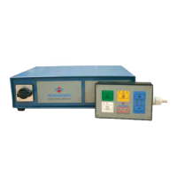
Details the ST100X controller's specifications: 230V operating voltage, integrated panel, plastic housing, rear connections, and current/power ratings.
Describes the ST200X controller: variable voltage, external push-button, metal housing, grounding, circuit protection, power ratings, and compact version availability.
Explains the function of push-buttons and indicator lights on ST controllers, detailing basic models for ST100 and ST200.
Details the basic push-button panel for ST100/ST200, including buttons (Magnetization, Demagnetization, Enabling) and indicator lights.
Describes the 2-level push-button panel for ST100/ST200, enabling different magnetization levels, including specific buttons and LEDs.
Details the 7-level push-button panel for ST200, allowing multiple magnetization levels, including specific buttons, LEDs, and sequence logic.
Explains the ST200 CH-ENABLE push-button panel for selecting discharge channels and magnetization levels, detailing button functions and LED status indications.
Covers electrical safety, grounding, protection switches, power supply requirements, and specific voltage needs for ST100 and ST200 controllers.
Details connecting ST100 controllers to a single-phase power supply, including cable requirements and transformer use for different voltages.
Explains connecting the ST100 controller to a single-phase supply, cable usage, and when a power transformer might be necessary.
Specifies the supplied multi-pole power cable for ST100, its length, and precautions for using longer cables to avoid voltage drop.
Addresses discharge cables for ST100, their standard length, and selecting longer cables to maintain voltage drop below 1%.
Lists electric specifications for ST100, including fuse details (12.5A lagged, 20x5 mm).
Details connecting ST200 controllers to single-phase or three-phase power supplies, including cable types and transformer requirements.
Explains connecting the ST200 controller to single-phase/three-phase supplies, cable use, and when a transformer is needed.
Specifies the supplied multi-pole power cable for ST200, its length, and precautions for using longer cables to ensure voltage drop below 1%.
Covers discharge cables for ST200, their standard length, and selecting longer cables to prevent overheating and voltage drop.
Lists electric specifications for ST200, including maximum power, voltage ratings (230V, 400V, 480V), and protection switch recommendations.
States ST100 controllers lack a specific enabling device but can be fitted with an optional one (see Chapter 6.1).
Describes the ST200's enabling device on the DB9 connector, its contact specifications, and connection for tool machine power and enabling cycles.
Details the optional external start button for ST100, its connector, technical specifications, and advice on using an auxiliary relay.
Explains optional 2-level and 7-level push-button panels for ST100/ST200, allowing remote connection for enhanced control.
Describes the QE version's optional external teleruptor, its power rating compatibility, installation requirements, and its role in efficient control.
Details the ST200's PLC interface connection via DB9, its function for control, enabling, and status indications, and available contacts.
Illustrates the physical connection of the ST100 controller to a magnetic module via a connector for miller applications.
Illustrates the physical connection of the ST100 controller to a magnetic module via a cable tie for grinder applications.
Provides diagrams for connecting ST200 controllers to magnetic chucks for 1, 2, 3, and 4 chuck configurations in miller applications.
Provides diagrams for connecting ST200 controllers to magnetic chucks for 1, 2, 3, and 4 chuck configurations in grinder applications.
Step-by-step guide for starting and operating the ST100 controller, including connection, powering up, and magnetization/demagnetization procedures.
Step-by-step guide for starting and operating ST200 controllers, covering connection, powering up, and magnetization/demagnetization procedures.
Highlights the importance of maintenance for unit longevity, performance, and functional safety.
Outlines safety measures for maintenance, including qualified personnel, disconnection, PPE, and avoiding hazardous conditions.
Specifies weekly maintenance tasks for operators, including inspection of indicator lights and buttons.
Details monthly maintenance tasks for qualified personnel, involving visual inspection of terminal boards, chucks, controllers, cables, and plugs.
Defines semi-annual maintenance: disconnecting discharge cables, measuring resistance/insulation, and reconnecting cables.
Defines extraordinary maintenance as operations not covered in the manual, requiring qualified and authorized personnel.
Informs that subsequent sections provide dimensional layouts and assembly instructions for troubleshooting and direct contact for queries.
Instructs to disconnect the unit from power supply and disassemble it from the machine if not used for extended periods.
Outlines user responsibility for dismantling and disposal according to UE directives and local laws, emphasizing safety and material separation.
Covers the 36-month warranty for defects in materials and workmanship, excluding on-site assistance costs and improper use.
Lists conditions that invalidate the warranty, such as non-payment, unauthorized repairs, serial number tampering, improper use, and disassembly.
| Category | Control Systems |
|---|---|
| Series | ST100 |
| Input Voltage | 24 VDC |
| Protection Class | IP20 |
| Weight | 0.5 kg |