
F
felicia78Aug 3, 2025
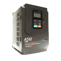
Why am I getting a CANopen packet error on my TECO-Westinghouse A510?
- FfitzpatrickvalerieAug 3, 2025
If you encounter a CANopen packet error with your TECO-Westinghouse Inverter, it could be due to a poor connection with the CANopen host terminal or the host not being connected when powered on. You can either continue transmission (expecting the packet transmission to return to normal or continue to have errors leading to disconnection) or power off the device. If you choose to power off, inspect the TB1 terminal and cable to ensure they are firmly connected. Also, verify that the transmission rate, maximum transmission distance, and cable length comply with ODVA specifications.