Do you have a question about the TECO TK1000 and is the answer not in the manual?
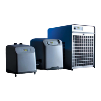
Lists the TK models (TK500, TK1000, TK2000) for which this replacement procedure is applicable.
Details the necessary tools like screwdrivers, wrenches, tongs, and parts like clamps and the motor fan itself.
Emphasizes qualified personnel, warns of electric shock, and instructs to disconnect power before proceeding.
Uses a screwdriver to remove four screws securing the metal grid, then removes the grid.
Uses an allen wrench to remove the fan blade screw and then the fan blade. Also removes red ring for specific models.
Uses a screwdriver to remove four INOX screws as indicated in the picture.
Removes the air filter grid and the air filter from their positions.
Lifts the red fan support from the bottom edge and places it on the metal cover.
Disconnects the compressor, heater, and probe connectors from the unit.
Fixes all cables in the fan support using five black clamps and tongs.
Disengages the fan connector and removes four nuts using an allen wrench (7).
Removes the old motor fan assembly and installs a new one, securing with nuts and connecting the fan connector.
Uses five black clamps to secure all electrical cables, replicating previous steps.
Reconnects all connectors, secures the fan support, and rebuilds the top part following a specific sequence.
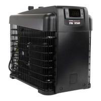
This document outlines the procedure for replacing the motor fan in TK500, TK1000, and TK2000 models of a chiller device. The chiller's primary function is to cool, and its maintenance involves specific steps for component replacement to ensure continued operation.
The device is a chiller, designed to regulate temperature, likely for an aquarium or similar application where maintaining a specific water temperature is crucial. The motor fan is a critical component of this system, responsible for air circulation and heat dissipation, which is essential for the chiller's efficient operation and to prevent overheating of internal components. The replacement process detailed in this guide ensures that the cooling function of the chiller can be restored or maintained if the original motor fan malfunctions.
The chiller models TK500, TK1000, and TK2000 are designed for ease of access for maintenance, as demonstrated by the step-by-step instructions for fan replacement. Users can identify the top conveyor, metal black grid, and red fan support, which are initial points of access for maintenance. The device incorporates air filter grids and air filters, indicating a design that considers air quality and the protection of internal components from dust and debris, which are crucial for prolonging the life and efficiency of the chiller. The presence of various connectors (compressor, heater, probe, and fan) suggests a modular design, allowing for individual component replacement and troubleshooting. The instructions emphasize the importance of proper reassembly, including the correct insertion of the front panel side into the aluminum profile, which highlights a design feature that ensures structural integrity and proper airflow.
The manual provides a comprehensive guide for replacing the motor fan, emphasizing safety and precision.
The detailed reassembly sequence ensures that the chiller is put back together correctly, maintaining its structural integrity and functional design. The specific instruction about inserting the front panel side into the aluminum profile during reassembly highlights a design feature that ensures proper alignment and fit. This comprehensive guide ensures that even complex maintenance tasks can be performed systematically and safely.