11
Instruction manual
6 ENG
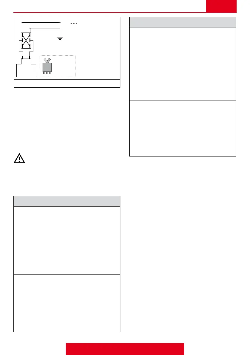
type
ON - OFF
+ 12V
_
General valve wiring diagram
Geoline connecting cables and control boxes are available
as optional extras.
HYDRAULIC CONNECTION
The valves of this series can be connected as follows:
- they can be connected to the group of cut-off valves
via pipes.
- they can be connected directly to the group of cut-off
valves
It is a good rule to install an inlet lter on the valve.
Observe the direction of the uid ow (Fig. 2-3-4)
and always make sure the pipes are tightly connected to
the valve casing.
The pipes used must comply with the characteristics given
in the TECHNICAL DATA table.
Hydraulic connection: VGME1 - VGME5
Connection to pipes (Fig.6-7):
- Put the “kit ange 6” together as indicated in g. 6
and insert it in the valve casing, securing it with the
related fork.
- Make sure all the blocking forks are inserted cor
-
rectly.
- Insert the outlet hose-holder tting, complete with
ring nut, in the “kit ange 6” (g.7).
- Insert the related pipes in the inlet, delivery and di
-
scharge ttings and secure them with an appropriate
clip (g.7).
Connection to the control unit (Fig.8):
- Insert the ange on the valve casing and secure it
with the related fork.
- Make sure the blocking forks of the ttings are inser
-
ted correctly.
- Connect the control unit to the general valve using
the dedicated tie-rods and blocking nuts.
- Insert the related pipes in the inlet and discharge
ttings and secure them with an appropriate clip.
SECOND PART (reserved for skilled technicians)
Hydraulic connection VGME4
Connection to pipes (Fig.9-10):
- Position the attachment bracket (example in g.12.).
- Insert the ange (complete with OR) on the valve
casing and secure it with screws and nuts (g.9)
- Make sure all the blocking forks are inserted cor
-
rectly.
- Insert the outlet hose-holder tting, complete with
ring nut, in the ange (g.10).
- Insert the related pipes in the inlet, delivery and dis
-
charge ttings and secure them with an appropriate
clip (g.10).
Connection to the control unit (Fig.11):
- Position the attachment bracket (example in g.12.).
- Make sure the blocking forks of the ttings are in
-
serted correctly.
- Connect the control unit to the general valve using
the dedicated tie-rods and blocking nuts.
- Insert the related pipes in the inlet and discharge
ttings and secure them with an appropriate clip.
 Loading...