The grinder is supplied already partially assembled.
1 - Base unit 11 - Washers for screws M5
2 - Arm-motor unit 12 - Arm securing screw M10x40
3 - Owner’s manual 13 - Washer for screw M10
4 - Test card 14 -Arm blocking handle
5 - Shield guard 15 -Arm securing nut M10
6 -
Grinding wheel Ø 5 3/4”x1/8”x7/8”
(145x3.2x22.2 mm)
16 -Operating handle
17 -Operating handle securing screw M6x25
7 -
Grinding wheel Ø 5 3/4”x3/16”x7/8”
(145x4.7x22.2 mm)
18 -Operating handle securing nut M6
19 -Sharpening template
8 -
Grinding wheel Ø 5 3/4”x1/4”x7/8”
(145x6x22.2 mm)
20 -Dressing brick
21 - 4 mm Allen wrench
9 - Extra shield guard 22 - 5 mm Allen wrench
10 -Guard securing screw M5x12
Hold the grinding wheel up by its central hole. Knock the edge of the grinding wheel
gently with a metal object. If it makes a numb non-metallic noise it means that
the wheel could be damaged:
Do not install the machine at eye level. You are recommended to install it at a height
of no more than 3.9 to 4.2 feet (1.2-1.3 m) from the oor.
The machine can be bench mounted or wall mounted.
- use 2 M8 screws complete with washers and nuts
(material not supplied), inserted in the securing holes F4. Make sure you position
the base unit on the bench as illustrated in the detail.
- to secure the arm-motor unit to the base unit, insert the V5
screw in the dedicated hole F5. Insert the R5 washer at the back and tighten the
knob M5.
- use two dowels with relative screws complete with
washers (material not supplied), inserted in the securing holes F6.
- to secure the arm-motor unit to the base unit, insert the V5
screw in the dedicated hole F5. Insert the R5 washer at the back and tighten the
nut D5.
- Insert the screw V7 in the relative hole in the arm and secure it with the nut D7.
- Completely screw the operating handle I7 on the screw V7.
Do not screw the screws too tight during this job to avoid cracking the guards.
- Remove the screw V8 and the ange F8 on the hub .
- Secure the guard P9, by screwing the screw V9, complete with washer R9, in the
relative hole F9 .
- Secure the arbor shield P10, by screwing the screw V10, complete with washer
R10, in the relative securing hole F10 .
The chain must be completely inspected before sharpening it to make sure it is intact.
Top part Connection link
Top cutting angle Left cutter
Side cutting angle Right cutter
Sharpening recess Driving link (pulling link)
Depth gauge Rivet
Bit
Heel
Rivet hole
- Before you start to sharpen, you need to know the type of chain and the relative
adjustment angles. These characteristics are written in the owner’s manual of the
chain saw on which the chain is tted or on the chain pack.
- The chain identication code is usually written on the driving link.
- You can also identify the chain using a template or gauge.
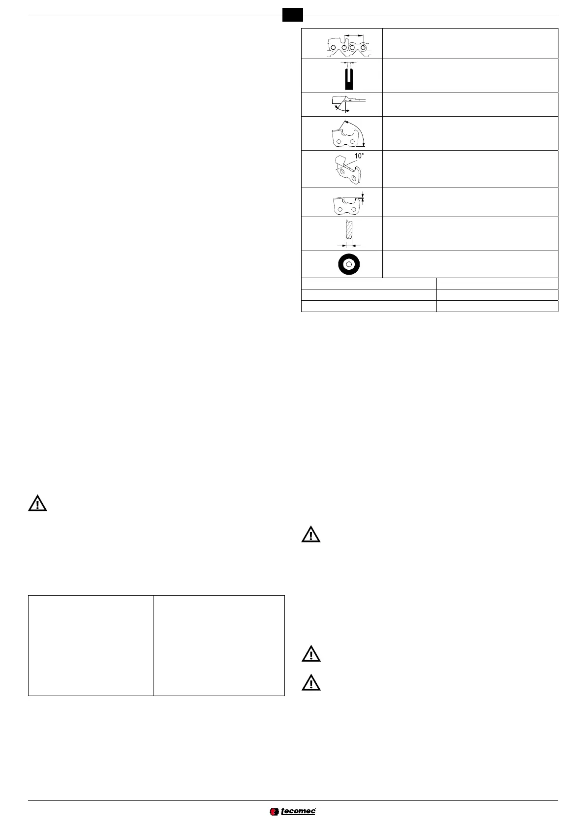
- Consult the CHAIN CHART at the end of this manual.
The columns in this chart provide the following information:
÷ 2
Chain pitch
Gauge
Top sharpening angle (vise rotation)
Cutting angle (arm rotation)
Down angle (vise inclination)
Gauge depth
Grinding wheel thickness
Grinding wheel code
Oregon chain codes Carlton chain codes
Windsor chain codes Stihl chain codes
SARP chain codes EM chain codes
a - Measure the gauge depth using the suitable shape.
b - Put the template on this side and measure the chain PITCH.
c - Put the template on this side to measure the cutter length.
d - The driving link width is measured using a suitable instrument (i.e. gauge).
- Use a grinding wheel suitable for the type of chain to be sharpened; consult the
chain chart at the end of the manual.
- Do not force the grinding wheel on the hub and do not alter the centering hole
diameter. Do not use grinding wheels that do not t perfectly in place.
- Use exclusively clean and perfect intact hub and ange to t the grinding wheel.
- Make sure the outside diameters of the hub and ange are identical.
- Loosen the screw V10 and turn the guard P10 .
- Choose the grinding wheel based on the type of chain to be sharpened (column H
in chain chart).
- Insert and perfectly center the grinding wheel in the dedicated seat on the hub
.
- Insert the ange F8 and tighten the screw V8.
If the grinding wheel is tted with the anges too tight, it could break during
use and put the operator at risk. To avoid such risk, tighten screw M6x25 to
If possible, check with dynamometric spanner.
- Close the guard again P10 and tighten the relative screw V10.
- Stand at the side of the grinding wheel, start the grinder and visually make sure
the grinding wheel does not oscillate sideways or crosswise, consequently causing
abnormal vibrations.
- If this should be the case, stop the machine immediately and check if the grinding
wheel has been tted correctly. If necessary, replace the grinding wheel with another
original one.
Always check a freshly tted grinding wheel at working speed for at least one
minute before you start grinding, standing at a safe distance and making sure
nobody else approaches the machine.
- Make sure the electrical system power supply complies with the values written on
the rating nameplate.
- The power supply voltage must not differ from that written on the nameplate by
±5%.
- The connection to the electric mains must be prepared subject to current standards
in force in the country in which the machine is used.
- The power socket used for the machine must have an earth wire, adequate fuse
and must be protected by a differential circuit breaker with tripping sensitivity no
higher than 30 mA.
 Loading...