35
Install dial indicator (Part No. 670241) equipped with
the correct tip on the extender leg. Use the small tip
for engines with timing dimensions of between Top
Dead Center and .050 (1.27 mm) BTDC . Use the
large tip for engines with timing dimensions of between
.051" (1.29 mm) BTDC to .150 (3.81 mm) BTDC.
Loosen the screw on the side of the adaptor sleeve
to allow the sleeve to be turned into the threads of
the spark plug hole, not the entire dial indicator. This
will ensure the proper location of the tip. Once the
adapter sleeve is secured in the hole, tighten screw
on sleeve adaptor to prevent the dial from moving
up or down, which would give a false reading.
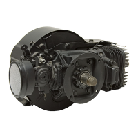
Find top dead center (TDC) by rotating the crankshaft
clockwise (when looking at the magneto end of the
crank) until the needle on the dial stops and reverses
direction. Where the needle stops is TDC. Loosen
the screw on the dial, and rotate the dial so that zero
is lined-up with the needle at TDC. Tighten the screw
on the dial to secure it in place.
T.D.C.
B.T.D.C.
DIAL SCREW
DIAL AT 0
DIAL AT .090” (2.29 mm) DIAL AT .080” (2.0 mm)
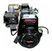
While watching the needle on the dial indicator, rotate
the crankshaft counterclockwise (when looking at the
magneto end of the crank) past the specified Before
Top Dead Center (BTDC) dimension. Then rotate
the crankshaft back clockwise to the proper dimension,
this will take out any slack between the connecting
rod and crankshaft assembly.
(Using .080 (2.0 mm) BTDC dimension as an example.)
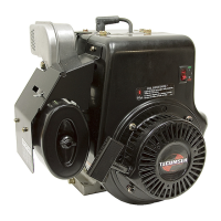
Next, disconnect the leads from the point terminal,
and be sure to reinstall the securing nut & tighten it
up. Connect one lead of a continuity light, or Ohmmeter
to the point terminal and the other lead to a good
ground. Loosen the two bolts holding down the stator
and rotate the stator until the continuity light or Ohmmeter
indicates a break in the circuit. At this point torque
down the stator bolts and the timing procedure is
completed.
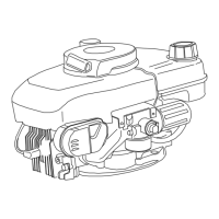
Before putting the dust cover back on the points box,
clean the points by sliding lint free paper back and
forth between the contacts. Manually, open the points
when removing the paper to eliminate paper fibers
from remaining between the contact points.
LINT FREE PAPER