52
3 Amp DC Alternator System - Diode in
Harness Sleeve
Models: H30-35, HS40, H50-60, HH50-60,
HM70-80-100, HHM80
This system has a diode included in the red wire which
converts the alternating current (A.C.) to direct current.
The direct current (D.C.) is used to provide a trickle charge
for the battery. The leads from the alternator and the type
of connector may vary, but the output readings will be
the same.
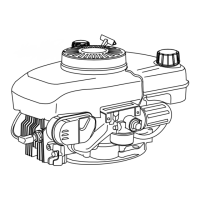
CHECKING THE SYSTEM: Remove the fuse from the
fuse holder and check the fuse to make certain it is good.
If faulty, replace with a six (6) AMP fuse.
To check D.C. output, separate the connectors at the
engine. Place the probe (+) in the red wire lead connector.
Ground the other probe to the engine (diag. 20).
With the engine running minimum values should read:
2500 R.P.M. - 8.0 Volts D.C.
3000 R.P.M. - 9.5 Volts D.C.
3300 R.P.M. -10.5 Volts D.C.
3600 R.P.M. -11.5 Volts D.C.
If these minimum readings are noted, the system is okay.
Check for bad battery, ammeter, wiring, etc.
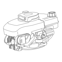
If less than the above readings, proceed to make an A.C.
output check by pulling back the protective coating from
the fuse holder and diode. Using an A.C. voltmeter, check
voltage from a point between the engine and the diode
as shown in the diagram (diag. 21).
With the engine running, minimum values should read:
2500 R.P.M. - 18.0 Volts A.C.
3000 R.P.M. - 22.0 Volts A.C.
3300 R.P.M. - 24.0 Volts A.C.
3600 R.P.M. - 26.0 Volts A.C.
If low or no voltage is experienced, replace the alternator.
If the alternator puts out the minimum A.C. voltage,
replace the diode.
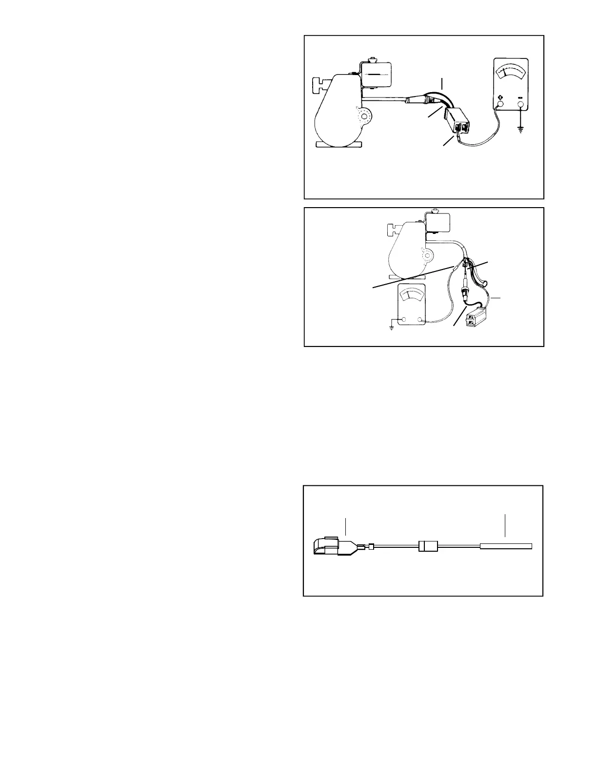
To replace the diode, disconnect at plug (spade terminal)
and cut the wire on the opposite end of the diode at the
solderless (crimped) connector. Remove 1/4" (6.35 mm)
of insulation from the cut end of the wire and twist the
strands together. Place the solderless connector from the
new diode onto the exposed 1/4" (6.35 mm) wire and
crimp the connector with a standard electricians pliers.
Reconnect plug end (or spade connector (diag. 22).
RED
GREEN
GROUND
PROBE (+)
20
22
21
RED
GREEN
DIODE
GROUND
PROBE (+)
FUSE HOLDER
SOLDERLESS
CONNECTOR
SPADE
CONNECTOR
Þ