29
5. Remove the fuel tank on TC type I engines by
unhooking the tank spring. For TC type II engines,
remove the self-locking nut and washer on the blower
housing stud and remove the fuel tank.
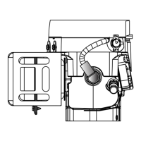
6. Remove the rewind starter assembly by removing three
machine screws (diag. 7-3). Remove the rubber plugs.
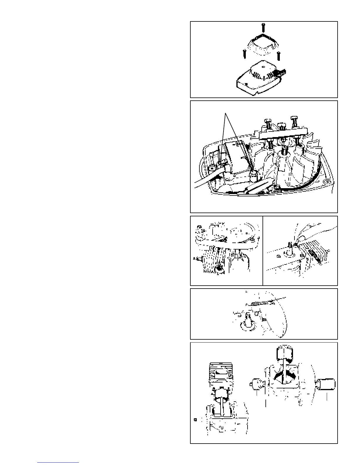
7. Remove the ignition grounding lead off the ignition
module and remove the ignition module using a 1/4"
socket or Torx T15 drive.
8. Use the strap wrench (part # 670305) to hold the
flywheel and loosen the flywheel nut until it is flush
with the end of the crankshaft.
9. Use flywheel puller (part # 670299) to pop the flywheel
off the crankshaft taper, unthread and remove the
puller. Remove the flywheel nut, washer, flywheel and
flywheel key (diag.7-4).
NOTE: DO NOT USE A KNOCK-OFF TOOL ON THE
CRANKSHAFT WHEN REMOVING THE FLYWHEEL.
PERMANENT ENGINE DAMAGE MAY RESULT.
10. Mark or note the location of the throttle link, governor
spring hook-up, and speed control to aid in assembly.
Remove the carburetor, spacer, gaskets, and air baffle
if equipped using a 1/4" socket on the carburetor studs.
11. Remove the blower housing base by removing the
three 5/16" hex head screws (diag. 7-5).
12. Attach the engine tool holder (part # 670300) to the
crankcase using the three removed blower housing
base hex head screws. Place tool in a bench vise (diag.
7-6).
13. Remove the muffler using a 12" (304 mm) piece of
heavy gauge wire with a 1/4" (6.31 mm) hook on one
end to pull the muffler spring off (diag. 7-7). A diagram
of the wire hook is in the tool section of this manual.
On TC type II engines, remove the shoulder bolts
holding the muffler on.
14. Note or mark the location of the cylinder to the
crankcase and remove the four Torx bolts holding the
cylinder to the crankcase using a six inch long Torx
T30 driver (part # 670320). Pull the cylinder off squarely
using caution so the rod does not bend. Use a 3/8"
open end wrench to loosen the four cylinder nuts on
early production type I engines (diag. 7-8).
15. Insert seal protector (part # 670301) to protect the
flywheel end oil seal and seal protector (part # 670303)
for the P.T.O. end oil seal (diag. 7-9).
16. Remove the crankcase cover screws and remove the
cover. On TC type II engines with a ball bearing in the
cover, the cover and crankshaft will be removed as an
assembly.
7-4
7-3
7-5
7-6
7-7
7-8
Mounting Screws
670301
670303
Not For Resale
www.SmallEngineDiscount.com
 Loading...