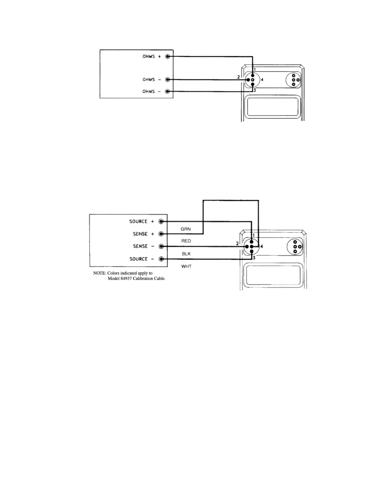
Figure 9. 3-Wire Resistance Simulation
Figure 10. 4-Wire Resistance Simulation
NOTE: To ensure accurate calibrator outputs, observe specified
limits to excitation currents. If in doubt, check current levels with
a DMM in series with either source lead (1 or 3).
NOTE: Due to limited display area, 100Ω and 1000Ω RTD's are
indicated on the display by a momentary readout of "RTD-100"
(or "RTD-1000") when first selected.
Thermistors are identified by a momentary alpha-numeric readout
of "Y-400" (signifying YSI Series-400 type thermistor).
Any of these readouts can be recalled by turning the unit off and
back on.
19