© 2016 tekmar 665
_
D - 06/16
11 of 28
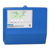
The control can be mounted on
a standard DIN rail. First remove
the control from its base and then,
using the hooks and spring clip
on the back of the control, mount
it onto the DIN rail. This will be a
popular option for those who prefer
to mount the control inside a larger
electrical panel.
The wiring can enter the
bottom or the back of the
enclosure. Knock-outs pro-
vided in the base allow the
wiring to be run in conduit
up to the enclosure. The
base also has holes that
line up with the mounting
holes of most common
electrical boxes.
Caution:
Do not run sensor wires parallel to telephone or power cables. If the sensor wires are located in an area with strong
sources of electromagnetic interference, shielded cable or twisted pair should be used or the wires can be run in a grounded metal
conduit. If using shielded cable, the shield wire should be connected to the Sensor Common terminal on the control and not to
earth ground.
All electrical wiring terminates in the two wiring chambers on the control. If the control is to be mounted on an electrical box, the
wiring can be roughed-in at the electrical box prior to installation of the control.
Power must not be applied to any of the wires during the rough-in wiring stage.
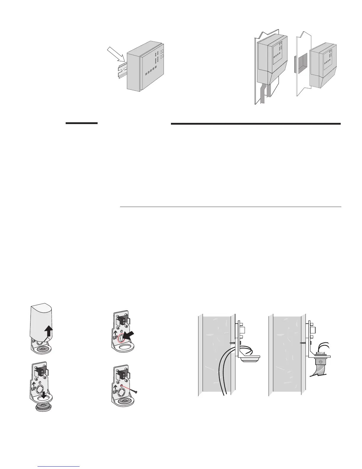
Mounting the Outdoor Sensor
STEP THREE
SENSOR INSTALLATION
The temperature sensor (thermistor) is built into the 070 enclosure.
• The 070 can be mounted directly onto a wall and the wiring should enter through the back or bottom of the enclosure. Do
not mount the 070 with the conduit knockout facing upwards as rain could enter the enclosure and damage the sensor.
•
In order to prevent heat transmitted through the wall from affecting the sensor reading, it may be necessary to install an
insulating barrier behind the enclosure.
• The 070 should be mounted on a northern wall, and should not be exposed to heat sources such as ventilation or window
openings.
• The 070 should be installed at an elevation above the ground that will prevent accidental damage or tampering.
Remove
cover by
sliding up-
wards away
from the
base.
To wire from
the back,
remove the
knock-out in
the sensor
base.
S1
S1
If using
conduit,
remove the
flexible plug
from the
base bottom.
S1
S1
Attach the
base to the
wall, soffit
or electrical
box.
S1
S1