12 of 28
© 2016 tekmar 665
_
D - 06/16
STEP FOUR
–––––––––
ROUGH-IN WIRING
All electrical wiring terminates in the control base wiring chamber. The base has standard 7/8” (22 mm) knockouts which accept
common wiring hardware and conduit fittings. Before removing the knockouts, check the wiring diagram and select those sections
of the chamber with common voltages. Do not allow the wiring to cross between sections as the wires will interfere with safety
dividers which should be installed at a later time.
• Power must not be applied to any of the wires during the rough-in wiring stage.
• All wires are to be stripped to a length of 3/8” (9mm) to ensure proper connection to the control.
• Install the Outdoor Sensor 070 and run the wiring back to the control.
• Install the Snow / Ice Sensor 090 according to the installation instructions in the Data Brochure D 090 and run the wiring back
to the control. See Data Brochure D 090 for very important details on sensor location and installation.
• If a Slab Sensor is used, install the slab sensor according to the installation instructions in the Data Brochure
provided with the sensor, and run the wiring back to the control.
• If a Remote Display Module (RDM) 040 is used, install the RDM according to the installation instructions in the Data Brochure
D 040 and run the wiring back to the control.
• If a Remote Start / Stop Module 039 is used, install the module according to the installation instructions in the Data Brochure
D 039 and run the wiring back to the control.
• Run wire from other system components (pumps, boiler, etc.) to the control.
• Run wires from the 115 V (ac) power to the control. Use a clean power source with a minimum 15 A circuit to ensure proper
operation. Multi-strand 16 AWG wire is recommended for all 115 V (ac) wiring due to its superior flexibility and ease of installation
into the terminals.
STEP FIVE
––––––––––
ELECTRICAL CONNECTIONS TO THE CONTROL
The installer should test to confirm that no voltage is present at any of the wires. Push the control into the base and slide it down
until it snaps firmly into place.
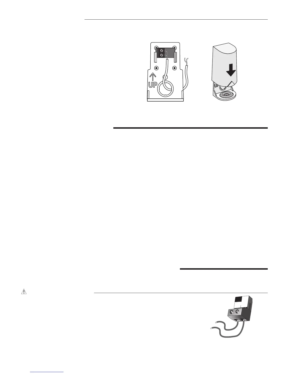
Powered Input Connections
115 V (ac) Power
Connect the 115 V (ac) power supply to the Power L and Power N terminals (16 and 17).
This connection provides power to the microprocessor and display of the control. As
well, this connection provides power to the Sys P1 terminal (15) from the Power L
terminal (16).
16
115 V (ac)
L
Power
L
N
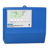
Wiring the Outdoor Sensor
Wires from
outdoor sensor
and sensor
common
terminals on
tekmar control
Sensor is built into
the enclosure
S1
S1
Slide cover back
over base
•
Connect 18 AWG or similar wire to the two termi-
nals provided in the enclosure and run the wires
from the 070 to the control. Do not run the wires
parallel to telephone or power cables. If the sensor
wires are located in an area with strong sources
of electromagnetic interference (EMI), shielded
cable or twisted pair should be used or the wires
can be run in a grounded metal conduit. If using
shielded cable, the shield wire should be con
-
nected to the Com terminal on the control and
not to earth ground.
•
Follow the sensor testing instruction in this brochure
and connect the wires to the control.
• Replace the front cover of the sensor enclosure.