21 of 36
Copyright © D 262 -12/08
Section
• • • •
• • •
• • •
• •
• •
•
• •
• •
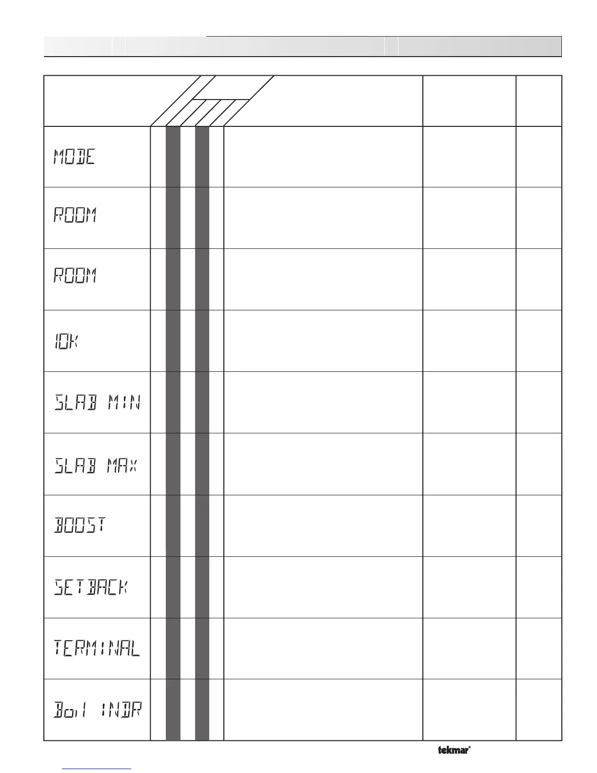
262 Adjust Menu (1 of 4)
The desired room air temperature during an
Occupied period.
Note: There is only a 13°F adjustment in the LTD
access level.
DIP switch =
Characterized Heating Curve
No RTU connected MODE = —1—
35 to 100˚F
(2 to 38˚C)
Default = 70°F (21°C)
35 to 100˚F
(2 to 38˚C)
Default = 65°F (18°C)
The desired room air temperature during an
UnOccupied period.
DIP switch =
Characterized Heating Curve
DIP switch =
Setback
No RTU connected
MODE = —1—
• •
NONE,
INDR (Indoor)
Zoin, SLAB
Default = NONE
The device that is to be connected to the 10K
input terminal.
DIP switch =
Characterized Heating Curve
No RTU connected
MODE = —1—
OFF, 35 to 120˚F
(OFF, 2 to 49˚C)
Default = 70°F (21°C)
40 to 150˚F
(4 to 66˚C)
Default = 90°F (32°C)
The minimum temperature at the slab sensor
DIP switch =
Characterized Heating Curve
No RTU connected
10K = SLAB Boil MIN = OFF
MODE = —1—
OFF, 0:20 to 8:00 hr
Default = OFF
The maximum temperature at the slab sensor.
DIP switch =
Characterized Heating Curve
No RTU connected
10K = SLAB Boil MIN = OFF
MODE = —1—
The amount of morning boost.
DIP switch =
Characterized Heating Curve
DIP switch =
Setback
No RTU connected
10K ≠ Zoin
MODE = —1—
The amount the boiler supply water temperature
will be reduced when the control is in the
UnOccupied mode.
DIP switch =
Reset Ratio
DIP switch =
Setback
MODE = — 1 —
0 to 50˚F
(0 to 28˚C)
Default = 15°F (8°C)
The type of terminal units that are being used in
the heating system.
DIP switch =
Characterized Heating Curve
MODE = —1—
HRF1 (Heavy), HRF2
(Light), (Fan-) COIL,
CONV (ector), RAD
(iator), BASE (board)
Default = CONV
The design indoor air temperature used in the
heat loss calculations for the heating system.
DIP switch =
Characterized Heating Curve
MODE = —1—
35 to 100˚F
(2 to 38˚C)
Default = 70°F (21°C)
Actual
Setting
• •
Sets the operating Mode for the control.
MODE —1— = (
Heating, DHW, and Setpoint)
MODE —2— = (
Dedicated DHW)
—1— or —2—
Default = MODE —1—
Occ
UnOcc
• •
LTD
USER
INST
ADV
Range
Access
Level
DescriptionItem Field
A
B1
B1
B2
B2
B2
B1
B1
B1
B1