Do you have a question about the Tekmar Mixing Control 361 and is the answer not in the manual?
Explains how to use the Item and Adjust buttons to navigate menus, view information, and modify settings on the LCD.
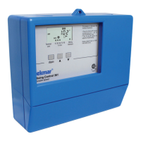
Identifies LCD display fields (Item, Number, Menu, Status) and provides a glossary for common operational symbols.
Covers control power-up, modes (Outdoor Reset, Setpoint), variable speed pump control, and boiler protection.
Details mixing demand, system pump operation, and indoor sensor use for temperature feedback and control.
Explains boiler contact activation, minimum boiler settings, and boiler protection features.
Covers powered input (120V AC, Mixing Demand) and output (System Pump, Var Pump, Boiler) connections.
Outlines testing of sensors, power supply, inputs, and outputs using a multimeter for verification.
Details the function of DIP switches (Advanced/Installer, Boiler Sensor) for control configuration.
Guides initial setup for Outdoor Reset and Setpoint Control, including temperatures and terminal units.
Explains the test routine for verifying control functions, outputs, and relays, including pausing and advancing.
Provides a systematic approach to diagnosing heating system issues, including information gathering and testing.
Lists common error codes, their causes, and solutions for diagnosing control faults.
| Category | Temperature Controller |
|---|---|
| Power Supply | 24 V (ac) ±10%, 50/60 Hz, 3 VA |
| Display | LCD |
| Enclosure Rating | NEMA 1 |
| Application | radiant floor heating, snow melting |
| Control Type | PID |
| Sensor Type | 10K thermistor |
| Input Type | 10k thermistor |
| Control Algorithm | PID |
| Operating Temperature Range | 32°F to 122°F (0°C to 50°C) |