© 2009 W 422 - 03/09 10 of 12
Troubleshooting the Wiring
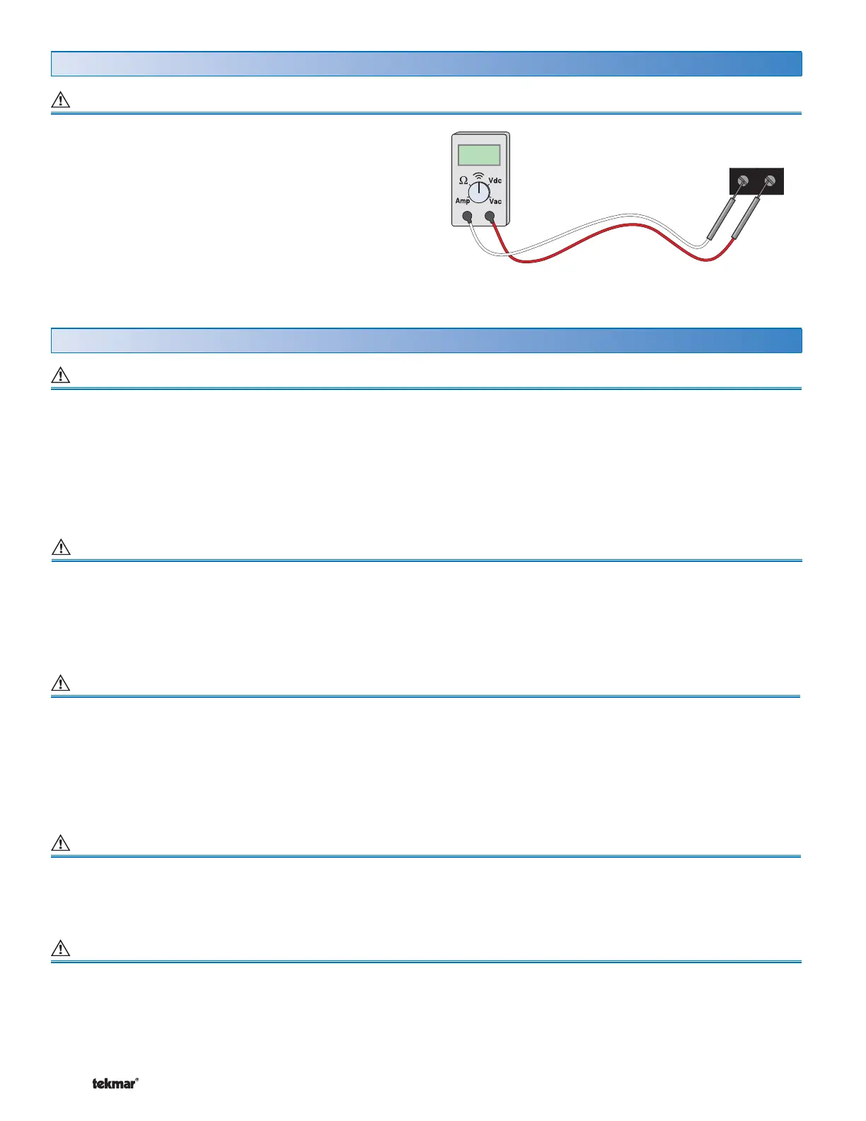
Test Meter
###
Control Terminals
The following tests are to be performed using standard
testing practices and procedures and should only be carried
out by properly trained and experienced persons.
A good quality electrical test meter, capable of reading from
at least 0-300 V (ac), 0-30 V (dc), 0-2,000,000 Ohms, and
testing for continuity is essential to properly test the wiring
and sensors.
General
Testing the Control Terminals 51-78
Testing Auxiliary 24 V Power Supply Terminals 57-58
Testing the Boiler Contact Terminals 51-52
Testing the DHW or Setpoint Demand Terminals 53-58
1. Shut off power to the control and the boiler circuit.
2. Remove the front cover from the control. Disconnect the
wires from the boiler contact (terminals 51-52).
3. Apply power to the control and press the Test button.
4. Use an electrical test meter and check for continuity
between terminals 51 and 52.
• When the burner symbol is displayed in the LCD, there
should be continuity.
• When the burner symbol is not displayed in the LCD,
there should be no continuity.
5. Reconnect the wires to the boiler contact (51-52), install
the front cover on the control and apply power to the
boiler circuit.
1. Remove the front cover from the control.
2. Use an electrical test meter to measure (ac) voltage
between the DHW Demand terminals (53-54) or the
Setpoint Demand terminals (55-56).
• When the demand device is on a voltage between 20 and
260 V (ac) should be measured between terminals and
the LCD should display “DEM” and “DHW” or “SETP”.
• When the demand device is off, less than 5 V (ac) should
be measured between the terminals.
1. Remove the front cover from the control.
2. Use an electrical test meter to measure (ac) voltage
between the Power R and Power C terminals 57 and
58 The reading should be 24 V (ac) + / – 10%.
3. If power is not present:
• Check the power supply to the Zone Manager and the
field replaceable fuse for the transformer on the Zone
Manager.
• If the fuse is blown, determine the cause of the failure
before replacing the fuse.
• Also check the Plug in connections on the underside of
the control.
Testing tN4 Network
To test the tN4 Network, check the wires for continuity.
1. Disconnect the two wires (tN4 and C) at one end and
connect them together.
2. Go to the other end of the wires and disconnect them.
3. Using an electrical test meter, check for continuity.
Testing Floating Action (power open / power closed) Terminals 61-63
1. Ensure that the control is set to operate the floating
action output.
2. Remove the front cover from the control.
3. Press the Test button.
4. When “OPN” is displayed in the LCD, use an electrical
test meter to measure the (ac) voltage between the C
and R Opn (Open) terminals (61-62). The reading should
be 24 V (ac) + / – 10%.
For an explanation on the use of the Test Button, the ‘Test’ sequence or any error messages, refer to the Data Brochure.
 Loading...