9 of 12 © 2009 W 422 - 03/09
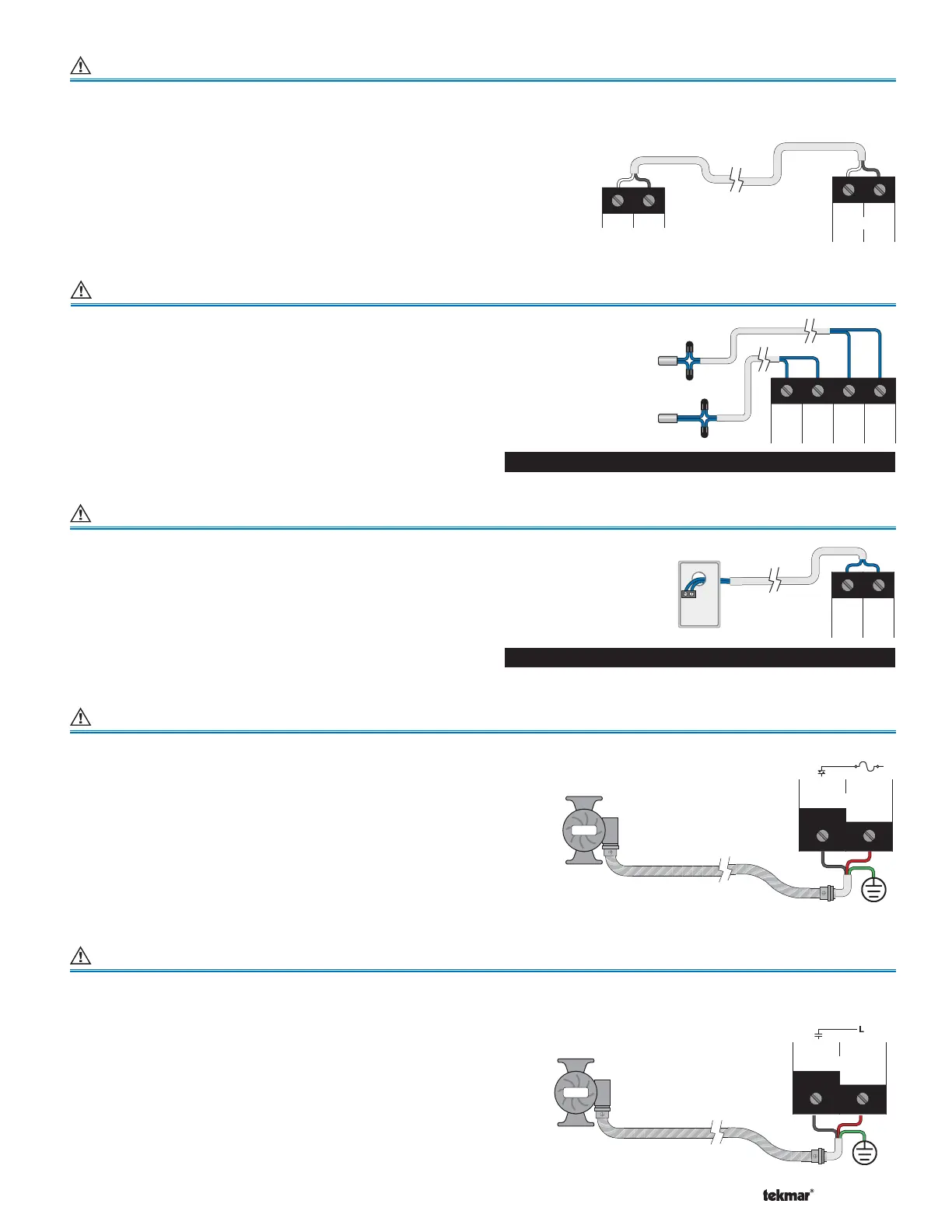
Wiring the Modulating Boiler Output Terminals 64-65
+-
Mod (dc)
64 65
Modulating Boiler or tekmar Stager
+-
• The control provides a 0-10 V (dc) modulating output to
a single modulating boiler or to a tekmar boiler staging
control that accepts an External Input Signal in place
of an outdoor sensor. (Example: 264, 265 and 268)
• Polarity is important.
• Connect the + wire from the boiler or staging control
to terminal 64 and the – wire from the boiler or staging
control to terminal 65.
Boiler and Mixed Sensor (tekmar 082) Terminals 66-69
Do Not Apply Power
Sensor mounted
on boiler pipe
Com Boil Mix Com
66 67 68 69
Sensor mounted
on mix supply pipe
Connect the two wires from the Boiler Sensor 082 to the
Com and Boil (66-67) terminals. The Boiler Sensor is used
by the control to measure the boiler water temperature.
Connect the two wires from the Mix Sensor 082 to the Com
and Mix (68-69) terminals. The Mix Sensor is used by the
control to measure the mix supply temperature.
Outdoor Sensor (tekmar 070) Terminals 69-70
Connect the two wires from the Outdoor Sensor 070 to the
Com and Out (69-70) terminals. The outdoor sensor is used
by the control to measure the outdoor air temperature.
Note: If an Outdoor Sensor 070 is connected to a tekmarNet
®
4
thermostat in the system, it is not required to be connected
to the control.
Note: Some modulating boilers may also require an on /
off signal in addition to the modulating signal. See terminals
51 and 52.
Wiring the Variable Speed Pump Terminals 73-74
Pump
Pump
L & N
73 74
Variable Speed
Pump N
The control varies the speed of a permanent capacitor,
impedance protected or equivalent pump motor that has
a locked rotor current of less than 2.4 A. Refer to Essay
E 021 for a listing of approved pumps.
If a variable speed injection pump is used, the pump is
wired directly to terminals 73 and 74.
The pump’s ground wire is connected to the ground screw
provided in the wiring chamber.
Wiring the Primary, DHW and Mixing System P1 Pump Terminals 71-72, 75-76, 77-78
The control operates a Primary Pump, a DHW Pump and
a Mixed System Pump (Mix Sys P1).
• If a Primary Pump is used, the pump is wired directly to
terminals 75 and 76.
• If a DHW Pump is used, the pump is wired directly to
terminals 71 and 72.
• If a Mixed System Pump is used, the pump is wired
directly to terminals 77 and 78.
• The pumps’ ground wires are connected to the ground
screw provided in the wiring chamber.
Pump
Pump
L & N
Note: For pumps larger than the control’s rated capacity,
an external isolation relay must be used.
75 76
Primary
Pump N
Sensor mounted on
exterior wall
Com Out
69 70
Do Not Apply Power
 Loading...