12 • IL573 Tek-ENTRY
®
Telephone Entry System Phone-Line Version Manual
Copyright © TekTone Sound & Signal Mfg., Inc. All Rights Reserved.
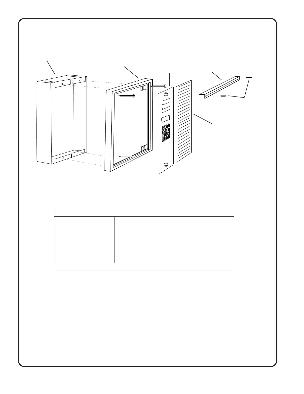
Figure 5—Frame and Housing Installation
FRAMES FLUSH MOUNT HOUSING
Wall Width Wall Height Wall
Model# Width Cut-out Model # Overall Cut-out Overall Cut-out Depth
OF191 6-1/4" - OH191 4-3/8" 4-1/2" 17-1/8" 17-1/4" 3-1/2"
OF192 10 1/4" - OH192 8-3/8" 8-1/2" 17-1/8" 17-1/4" 3-1/2"
OF193 14-1/4" - OH193 12-3/8" 12-1/2" 17-1/8" 17-1/4" 3-1/2"
OF194 18-1/4" - OH194 16-3/8" 16-1/2" 17-1/8" 17-1/4" 3-1/2"
OF195 22-1/4" - OH195 20-3/8" 20-1/2" 17-1/8" 17-1/4" 3-1/2"
OF196 26-1/4" - OH196 24-3/8" 24-1/2" 17-1/8" 17-1/4" 3-1/2"
For more than 240 suites, contact factory for frame and housing information. Directories supplied separately.
TE Series Master Housing & Frame Chart
OH192
Housing
OF192
Frame
Frame
Bracket
AM190D
Directory
Vandal
Resistant
Screws
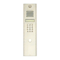
TE905A
Notes:
1. Refer to frame and housing chart for wall cut-out dimensions.
2. AM190D directory panels have 60 name capacity. For additional directories, size the frame and
housing accordingly. (Example: 1-TE905A + 2-AM190D would require an OF/OH193, 1-TE905A+3-
AM190D would require an OF/OH194, 1-TE905A+0-AM190D would require an OF/OH191.)
3. Flush mounting frame shown in diagram above.
4. Frame bracket supplied with OF192. Bracket is supplied with scrulox screws, but it is suggested you
use the spanner type vandal-resistant screws supplied with the TE905A. Use TekTone
®
driver
#HT007.
5. Refer to Figure 4—PM900 Control Unit Mounting Template to mount the PM900 Control Unit inside
the housing.