CIRCUIT DESCRIPTION
Section 3—475
Introduction
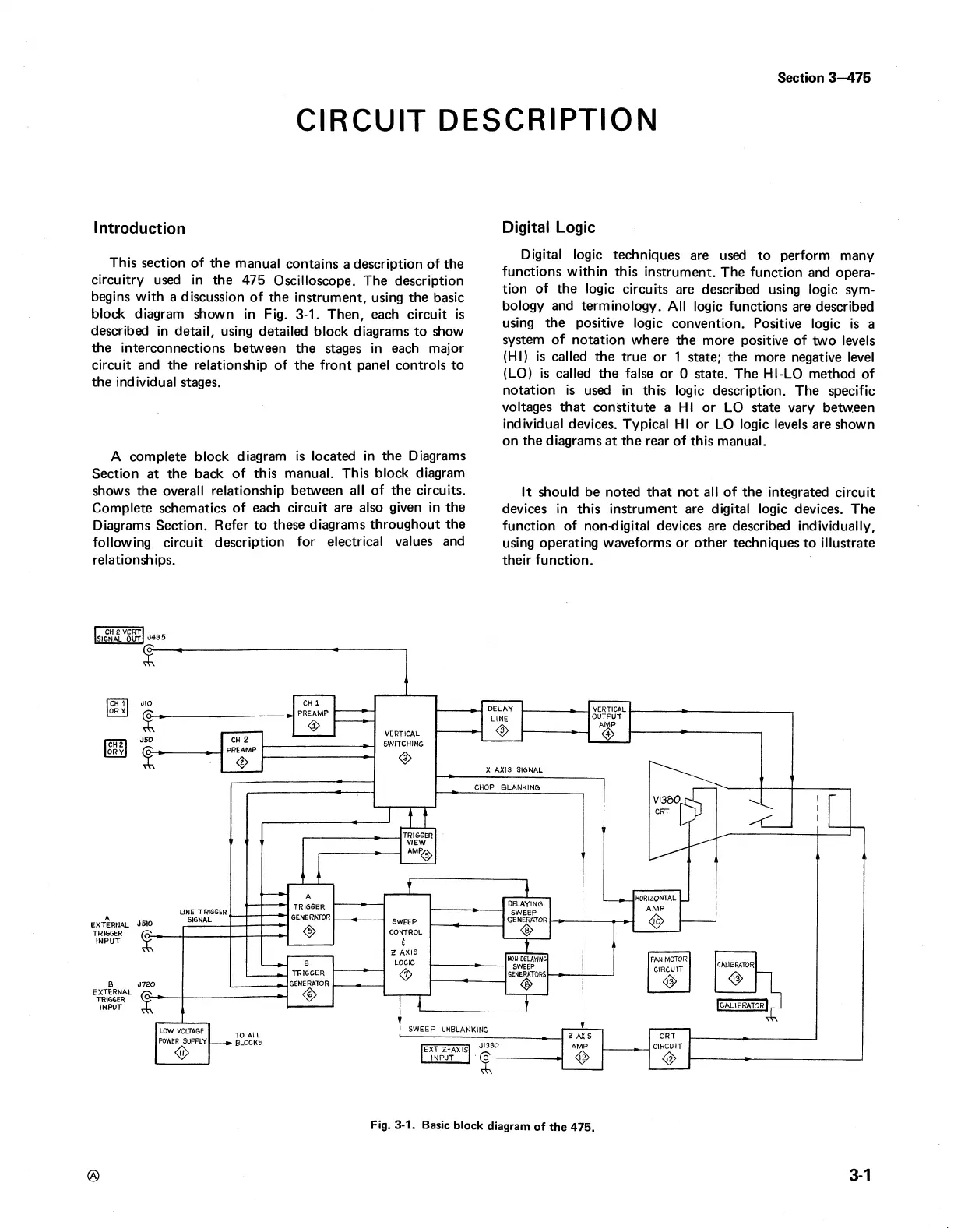
This section of the manual contains a description of the
circuitry used in the 475 Oscilloscope. The description
begins with a discussion of the instrument, using the basic
block diagram shown in Fig. 3-1. Then, each circuit is
described in detail, using detailed block diagrams to show
the interconnections between the stages in each major
circuit and the relationship of the front panel controls to
the individual stages.
A complete block diagram is located in the Diagrams
Section at the back of this manual. This block diagram
shows the overall relationship between all of the circuits.
Complete schematics of each circuit are also given in the
Diagrams Section. Refer to these diagrams throughout the
following circuit description for electrical values and
relationships.
Digital Logic
Digital logic techniques are used to perform many
functions within this instrument. The function and opera
tion of the logic circuits are described using logic sym
bology and terminology. All logic functions are described
using the positive logic convention. Positive logic is a
system of notation where the more positive of two levels
(HI) is called the true or 1 state; the more negative level
(LO) is called the false or 0 state. The HI-LO method of
notation is used in this logic description. The specific
voltages that constitute a HI or LO state vary between
individual devices. Typical HI or LO logic levels are shown
on the diagrams at the rear of this manual.
It should be noted that not all of the integrated circuit
devices in this instrument are digital logic devices. The
function of non-digital devices are described individually,
using operating waveforms or other techniques to illustrate
their function.
®
3-1
Fig. 3-1. Basic block diagram of the 475.