Circuit Description—475
The Z Axis Amplifier circuit determines the CRT
intensity and blanking. The Z Axis Amplifier circuit sums
the current inputs from the INTENSITY control, the
Vertical Channel Switching circuit (chopped blanking), the
Z Axis Logic circuit (unblanking), and the external Z AXIS
INPUT connector. The output level of the Z Axis Amplifier
circuit controls the trace intensity through the CRT circuit.
The CRT circuit provides the voltages and contains the
controls necessary for operation of the cathode-ray tube.
The Power Supply circuit provides the low voltage
power necessary for operation of this instrument. This
voltage is distributed to all of the circuits in the instrument
as shown by the Power Distribution Diagram. The Cali
brator circuit provides a square-wave output with accurate
voltage and current amplitudes, which can be used to check
the calibration of the instrument and the compensation of
probes. The CALIBRATOR current loop provides an
accurate current source for calibration of current measuring
probe systems.
CHANNEL 1 PREAMP
General
Input signals for vertical deflection on the CRT can be
connected to the CH 1 OR X input connector. In the X-Y
mode of operation, the input signal connected to the CH 1
OR X connector provides the horizontal (X-axis) deflection
(TIM E/DIV switch set to X-Y, VERT MODE switch set to
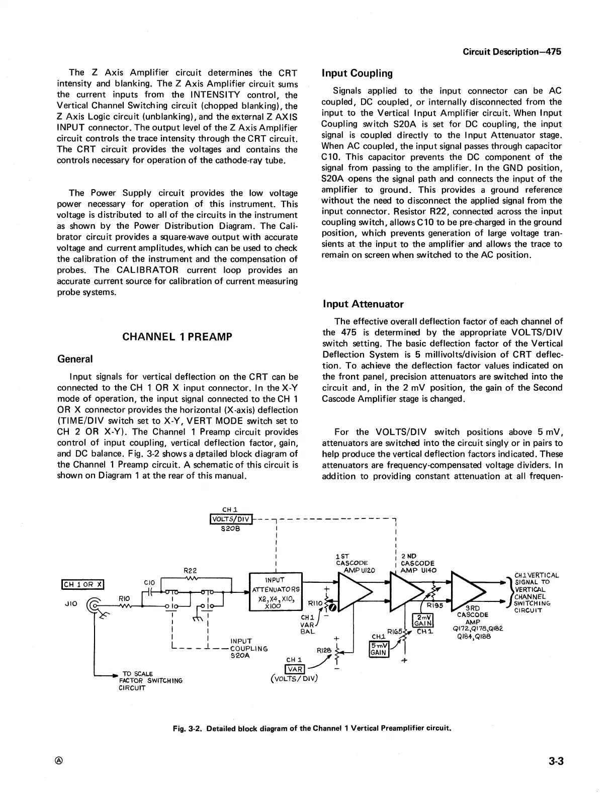
CH 2 OR X-Y). The Channel 1 Preamp circuit provides
control of input coupling, vertical deflection factor, gain,
and DC balance. Fig. 3-2 shows a detailed block diagram of
the Channel 1 Preamp circuit. A schematic of this circuit is
shown on Diagram 1 at the rear of this manual.
Input Coupling
Signals applied to the input connector can be AC
coupled, DC coupled, or internally disconnected from the
input to the Vertical Input Amplifier circuit. When Input
Coupling switch S20A is set for DC coupling, the input
signal is coupled directly to the Input Attenuator stage.
When AC coupled, the input signal passes through capacitor
CIO. This capacitor prevents the DC component of the
signal from passing to the amplifier. In the GND position,
S20A opens the signal path and connects the input of the
amplifier to ground. This provides a ground reference
without the need to disconnect the applied signal from the
input connector. Resistor R22, connected across the input
coupling switch, allows CIO to be pre-charged in the ground
position, which prevents generation of large voltage tran
sients at the input to the amplifier and allows the trace to
remain on screen when switched to the AC position.
Input Attenuator
The effective overall deflection factor of each channel of
the 475 is determined by the appropriate VOLTS/DIV
switch setting. The basic deflection factor of the Vertical
Deflection System is 5 millivolts/division of CRT deflec
tion. To achieve the deflection factor values indicated on
the front panel, precision attenuators are switched into the
circuit and, in the 2 mV position, the gain of the Second
Cascode Amplifier stage is changed.
For the VOLTS/DIV switch positions above 5 mV,
attenuators are switched into the circuit singly or in pairs to
help produce the vertical deflection factors indicated. These
attenuators are frequency-compensated voltage dividers. In
addition to providing constant attenuation at all frequen-
C H l
Fig. 3-2. Detailed block diagram of the Channel 1 Vertical Preamplifier circuit.
®
3-3
 Loading...


