Circuit Description—475
offset compensation changes associated with variations in
ambient temperature. As temperature increases, the value
of RT170 decreases. This results in a decrease in voltage
across CR170 and CR174. CR170 and CR174 are voltage-
variable capacitance semiconductors whose capacitance
increases with a decrease in reverse voltage across them.
Thus, CR170 and CR174 will provide more peaking at
higher temperatures. L178 is a toroid inductor that cancels
high-frequency common-mode signals generated by the
previous stages. The Channel 1 Position Centering adjust
ment centers the range of control of the Channel 1
POSITION control.
CHANNEL 2 PREAMP
General
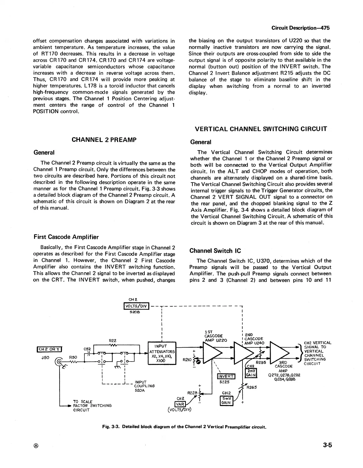
The Channel 2 Preamp circuit is virtually the same as the
Channel 1 Preamp circuit. Only the differences between the
two circuits are described here. Portions of this circuit not
described in the following description operate in the same
manner as for the Channel 1 Preamp circuit. Fig. 3-3 shows
a detailed block diagram of the Channel 2 Preamp circuit. A
schematic of this circuit is shown on Diagram 2 at the rear
of this manual.
First Cascode Amplifier
Basically, the First Cascode Amplifier stage in Channel 2
operates as described for the First Cascode Amplifier stage
in Channel 1. However, the Channel 2 First Cascode
Amplifier also contains the INVERT switching function.
This allows the Channel 2 signal to be inverted as displayed
on the CRT. The INVERT switch, when pushed, changes
the biasing on the output transistors of U220 so that the
normally inactive transistors are now carrying the signal.
Since their outputs are cross-coupled from side to side the
output signal is of opposite polarity to that available in the
normal (button out) position of the INVERT switch. The
Channel 2 Invert Balance adjustment R215 adjusts the DC
balance of the stage to eliminate baseline shift in the
display when switching from a normal to an inverted
display.
VERTICAL CHANNEL SWITCHING CIRCUIT
General
The Vertical Channel Switching Circuit determines
whether the Channel 1 or the Channel 2 Preamp signal or
both will be connected to the Vertical Output Amplifier
circuit. In the ALT and CHOP modes of operation, both
channels are alternately displayed on a shared-time basis.
The Vertical Channel Switching Circuit also provides several
internal trigger signals to the Trigger Generator circuits, the
Channel 2 VERT SIGNAL OUT signal to a connector on
the rear panel, and the chopped blanking signal to the Z
Axis Amplifier. Fig. 3-4 shows a detailed block diagram of
the Vertical Channel Switching Circuit. A schematic of this
circuit is shown on Diagram 3 at the rear of this manual.
Channel Switch 1C
The Channel Switch 1C, U370, determines which of the
Preamp signals will be passed to the Vertical Output
Amplifier. The push-pull Preamp signals connect between
pins 2 and 3 (Channel 2) and between pins 10 and 11
CH2
j volts/ d iv "! *
S20B
CH2 VERTICAL
SIGNAL TO
VERTICAL
CHANNEL
SWITCHING
CIRCUIT
®
3-5
Fig. 3-3. Detailed block diagram of the Channel 2 Vertical Preamplifier circuit.
 Loading...


