Calibration—475
4. Check Channel 2 Inverted Balance
a. Set the VERT MODE switch to CH 2 and the CH 2
AC-GND-DC switch to GND.
b. Position the trace to the center horizontal line with
the CH 2 POSITION control.
c. Push the INVERT switch.
d. CHECK—Trace does not vertically shift more than 1
division between the positions of the INVERT switch.
5. Check Channel 1 and 2 Position Range
a. Connect the Standard Amplitude Calibrator output
to the CH 1 and CH 2 inputs via a 42-inch 50 12 BNC cable
and a dual input coupler.
b. Set both VO LTS/DIV switches to 2 mV and both
AC-GND-DC switches to AC.
c. Adjust the Standard Amplitude Calibrator for a
50 mV output.
d. CHECK—That the top of the CRT display can be
positioned below the center horizontal line, and the bottom
of the display can be positioned above the center hori
zontal line.
e. Set the VERT MODE switch to CH 1.
f. CHECK—That the top of the CRT display can be
positioned below the center horizontal line, and the bottom
of the display can be positioned above the center horizontal
line.
6. Check Channel 1 and 2 Gain
a. Set both VOLTS/DIV switches to 5.mV.
b. Adjust the Standard Amplitude Calibrator for a
20 mV square-wave output.
c. CHECK—CRT display for 4 divisions of deflection,
within 0.12 division.
d. Set the VERT MODE switch to CH 2.
e. CHECK—CRT display for 4 divisions of deflection,
within 0.12 division.
7. Check Add Mode Operation
a. Set both AC-GND-DC switches to DC.
b. Adjust the Standard Amplitude Calibrator for a
10 mV output.
c. Set the VERT MODE switch to ADD.
d. CHECK—CRT display for 4 divisions, within 0.12
division, of amplitude.
8. Check Channel 1 and 2 Deflection Accuracy
a. Set the VERT MODE switch to CH 1 and the CH 2
AC-GND-DC switch to GND.
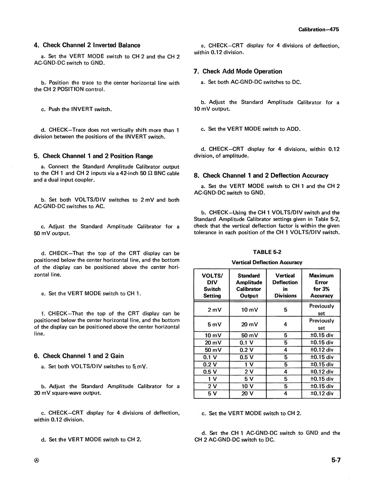
b. CHECK—Using the CH 1 VOLTS/DIV switch and the
Standard Amplitude Calibrator settings given in Table 5-2,
check that the vertical deflection factor is within the given
tolerance in each position of the CH 1 VOLTS/DIV switch.
TABLE 5-2
Vertical Deflection Accuracy
VOLTS/
Standard Vertical
Maximum
DIV
Amplitude Deflection Error
Switch
Calibrator
in
for 3%
Setting
Output Divisions
Accuracy
2 mV
10 mV 5
Previously
set
5 mV
20 mV
4
Previously
set
10 mV
50 mV
5
±0.15 div
20 mV 0.1 V
5
±0.15 div
50 mV
0.2 V 4
±0.12 div
0.1 V
0.5 V
5
±0.15 div
0.2 V
1 V
5
±0.15 div
0.5 V
2 V
4
±0.12 div
1 V
5 V
5
±0.15 div
2 V
10 V
5
±0.15 div
5 V
20 V 4
±0.12 div
c. Set the VERT MODE switch to CH 2.
d. Set the CH 1 AC-GND-DC switch to GND and the
CH 2 AC-GND-DC switch to DC.
5-7