Calibration-475
2. Connect the autotransformer to a suitable power
source.
5. Set the controls as given under Preliminary Control
Settings (given prior to Part I—Performance Check). Allow
at least 20 minutes warmup before proceeding.
3. Connect the 475 to the autotransformer output.
NOTE
4. Set the auto transformer output voltage to the center
of the voltage range selected by the Line Voltage Selector.
Titles for external controls of this instrument are
capitalized in this procedure (e.g., INTENSITY).
Internal adjustments are initial capitalized only (e.g.,
CRT Grid Bias).
POWER SUPPLY CALIBRATION
Equipment Required
1. Precision DC Voltmeter
4. Three-inch Screwdriver
2. DC Voltmeter
3. Test Oscilloscope
5. Variable Auto-Transformer
Control Settings
Preset instrument controls to the settings given under
Preliminary Control Settings.
1- Check Power Supply DC Levels and Ripple
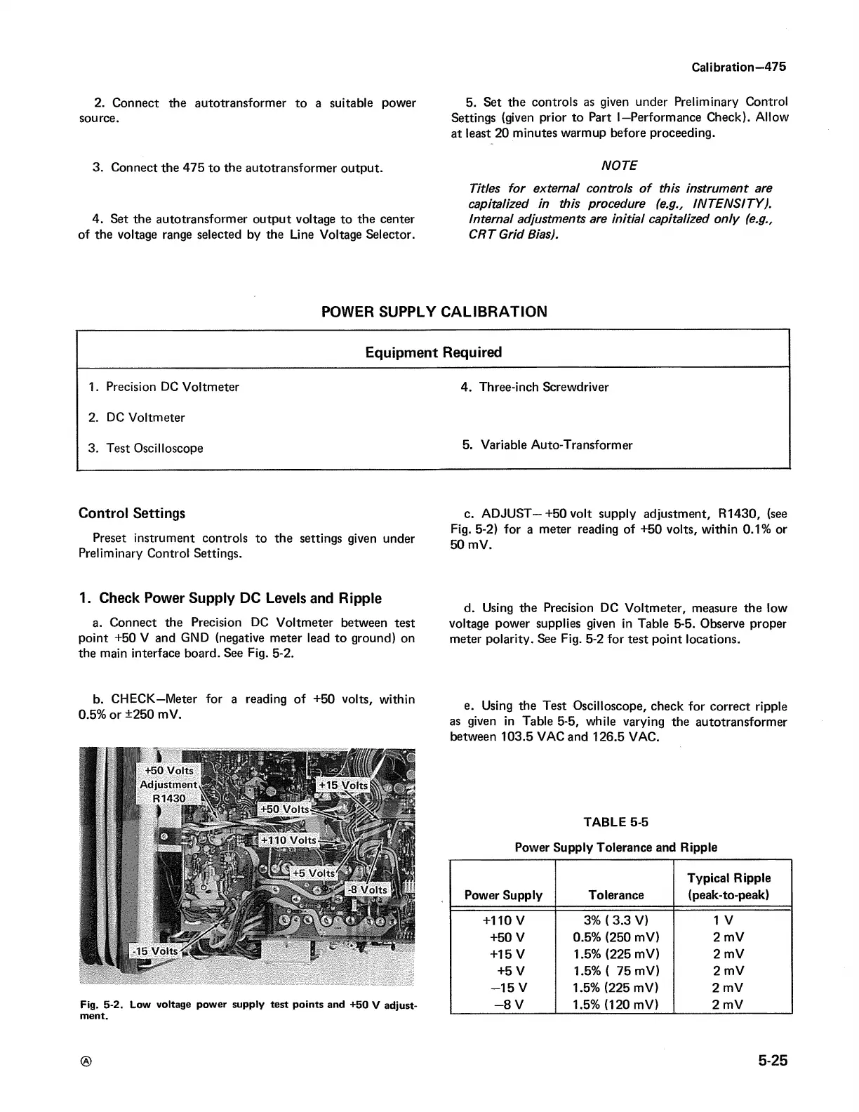
a. Connect the Precision DC Voltmeter between test
point +50 V and GND (negative meter lead to ground) on
the main interface board. See Fig. 5-2.
c. ADJUST—+50 volt supply adjustment, R1430, (see
Fig. 5-2) for a meter reading of +50 volts, within 0.1% or
50 mV.
d. Using the Precision DC Voltmeter, measure the low
voltage power supplies given in Table 5-5. Observe proper
meter polarity. See Fig. 5-2 for test point locations.
b. CHECK—Meter for a reading of +50 volts, within
0.5% or +250 mV.
Fig. 5-2. tow voltage power supply test points and +50 V adjust
ment.
e. Using the Test Oscilloscope, check for correct ripple
as given in Table 5-5, while varying the autotransformer
between 103.5 VAC and 126.5 VAC.
TABLE 5-5
Power Supply Tolerance and Ripple
Power Supply
Tolerance
Typical Ripple
(peak-to-peak)
+110 V 3% (3.3 V)
1 V
+50 V 0.5% (250 mV)
2 mV
+15 V
1.5% (225 mV)
2 mV
+5 V 1.5% ( 75 mV)
2 mV
-1 5 V
1.5% (225 mV)
2 mV
- 8 V
1.5% (120 mV)
2 mV
5-25