4. Check ASTIG Control
a. Rotate ASTIG control (front panel screwdriver adjust
ment) through its range.
b. CHECK—For dot de-focus at both extremes of the
ASTIG control.
c. Reset the ASTIG control for a well-defined dot.
5. Check Display Controls
a. Rotate SCALE ILLUM control through its range.
b. CHECK—For a smooth increase in illumination.
c. Set the INTENSITY control to mid-range.
d. Rotate the FOCUS control through its range.
e. CHECK—For trace de-focus at both extremes of the
FOCUS control.
f. Rotate the INTENSITY control from fully counter
clockwise to fully clockwise.
g. CHECK—For trace intensity to increase smoothly
from minimum to maximum intensity.
h. Reset the INTENSITY and FOCUS controls for a
well-defined trace.
6. Adjust Trace Alignment
a. Position the trace to the center horizontal graticule
line.
b. CHECK—That the trace is parallel with the center
horizontal line.
c. ADJUST-TRACE ROTATION adjustment (front
panel adjustment) to make the trace parallel to the center
horizontal line.
7. Adjust Y Axis Alignment
a. Connect 0.1 ms time marks from the Time-Mark
Generator (Type 2901) to the CH 1 input via a 42-inch
50 £2 BNC cable and a 50 12 BNC termination.
Calibration—475
b. Set the CH 1 AC-GND-DC switch to DC and the CH 1
VO LTS/DIV switch to 0.1 V.
c. Adjust the A LEVEL control for a stable display, the
ASTIG and FOCUS controls for a well-defined display.
d. Adjust the VAR T IM E /D IV control for 1 time
marker/division.
e. CHECK—For no more than 0.1 division of tilt of the
center time marker as compared with the center vertical
graticule line.
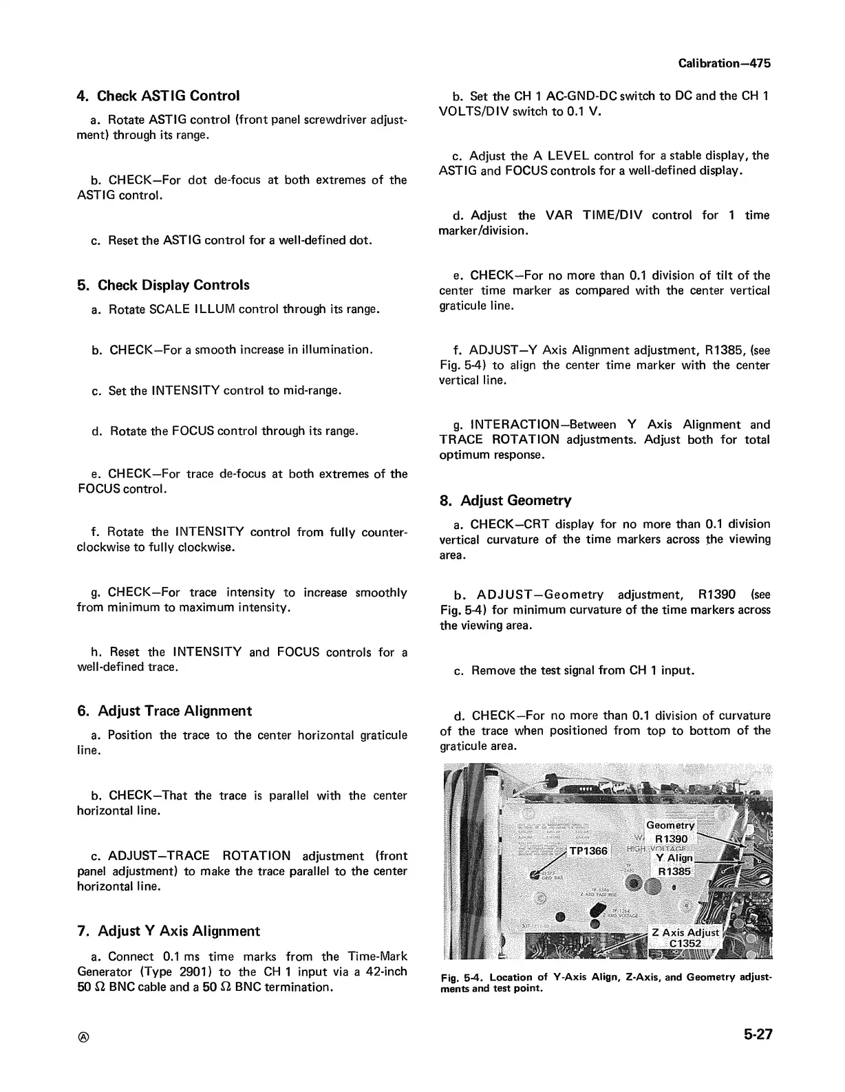
f. ADJUST—Y Axis Alignment adjustment, R1385, (see
Fig. 5-4) to align the center time marker with the center
vertical line.
g. INTERACTION—Between Y Axis Alignment and
TRACE ROTATION adjustments. Adjust both for total
optimum response.
8. Adjust Geometry
a. CHECK—CRT display for no more than 0.1 division
vertical curvature of the time markers across the viewing
area.
b. A D JU S T —Geometry adjustment, R1390 (see
Fig. 5-4) for minimum curvature of the time markers across
the viewing area.
c. Remove the test signal from CH 1 input.
d. CHECK—For no more than 0.1 division of curvature
of the trace when positioned from top to bottom of the
graticule area.
Fig. 5-4. Location of Y-Axis Align, Z-Axis, and Geometry adjust
ments and test point.
5-27