h. Turn the CH 2 VOLTS/DIV switch to 10 mV.
i. CHECK—Repeat step 32-d.
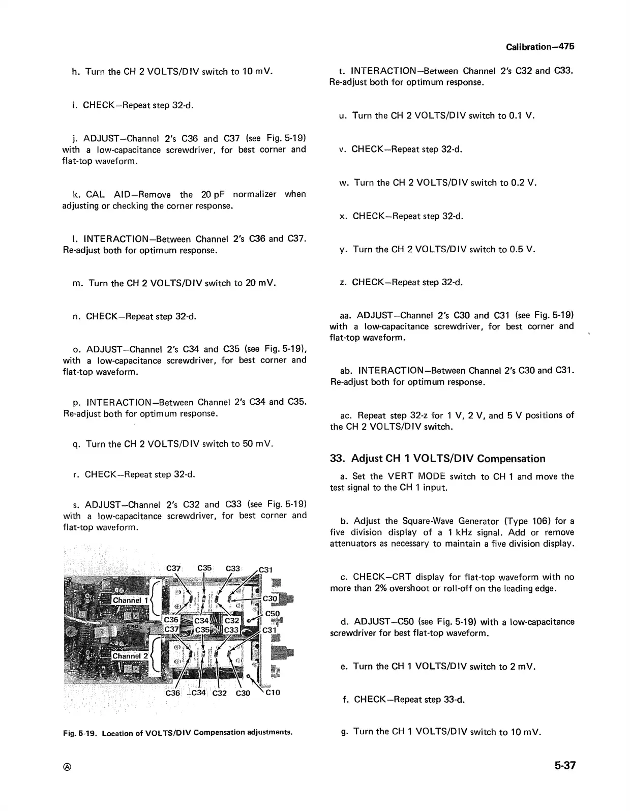
j. ADJUST—Channel 2's C36 and C37 (see Fig. 5-19)
with a low-capacitance screwdriver, for best corner and
flat-top waveform.
k. CAL A ID —Remove the 20 pF normalizer when
adjusting or checking the corner response.
l. INTERACTION—Between Channel 2's C36 and C37.
Re-adjust both for optimum response.
m. Turn the CH 2 VO LTS/DIV switch to 20 mV.
n. CHECK—Repeat step 32-d.
o. ADJUST—Channel 2's C34 and C35 (see Fig. 5-19),
with a low-capacitance screwdriver, for best corner and
flat-top waveform.
p. INTERACTION—Between Channel 2's C34 and C35.
Re-adjust both for optimum response.
q. Turn the CH 2 VOLTS/DIV switch to 50 mV.
r. CHECK—Repeat step 32-d.
s. ADJUST—Channel 2's C32 and C33 (see Fig. 5-19)
with a low-capacitance screwdriver, for best corner and
flat-top waveform.
Fig. 5-19. Location of VOLTS /DIV Compensation adjustments.
Calibration-475
t. INTERACTION—Between Channel 2's C32 and C33.
Re-adjust both for optimum response.
u. Turn the CH 2 VO LTS/DIV switch to 0.1 V.
v. CHECK—Repeat step 32-d.
w. Turn the CH 2 VOLTS/DIV switch to 0.2 V.
x. CHECK—Repeat step 32-d.
y. Turn the CH 2 VOLTS/DIV switch to 0.5 V.
z. CHECK—Repeat step 32-d.
aa. ADJUST—Channel 2's C30 and C31 (see Fig. 5-19)
with a low-capacitance screwdriver, for best corner and
flat-top waveform.
ab. INTERACTION—Between Channel 2's C30 and C31.
Re-adjust both for optimum response.
ac. Repeat step 32-z for 1 V, 2 V, and 5 V positions of
the CH 2 VOLTS/DIV switch.
33. Adjust CH 1 VOLTS/DIV Compensation
a. Set the VERT MODE switch to CH 1 and move the
test signal to the CH 1 input.
b. Adjust the Square-Wave Generator (Type 106) for a
five division display of a 1 kHz signal. Add or remove
attenuators as necessary to maintain a five division display.
c. CHECK—CRT display for flat-top waveform with no
more than 2% overshoot or roll-off on the leading edge.
d. ADJUST—C50 (see Fig. 5-19) with a low-capacitance
screwdriver for best flat-top waveform.
e. Turn the CH 1 VO LTS/DIV switch to 2 mV.
f. CHECK—Repeat step 33-d.
g. Turn the CH 1 VO LTS/DIV switch to 10 mV.
©
5-37