ACCESSORIES
Operational Accessories
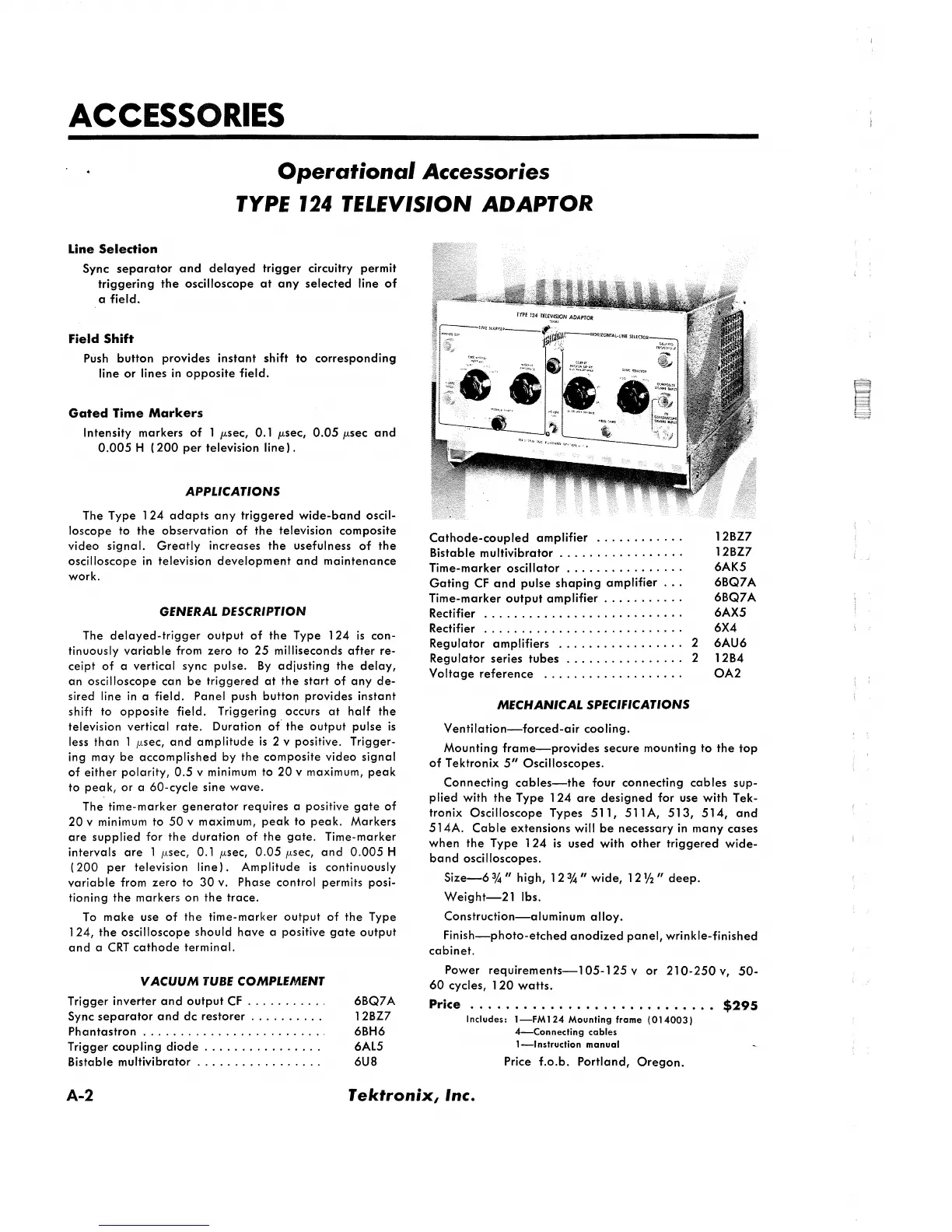
TYPE 124 TELEVISION ADAPTOR
Line Selection
Sync separator and delayed trigger circuitry permit
triggering the oscilloscope at any selected line of
a field.
Field Shift
Push button provides instant shift to corresponding
line or lines in opposite field.
Gated Time Markers
Intensity markers of 1 /xsec, 0.1 /xsec, 0 .0 5 /xsec and
0.005 H (200 per television line).
APPLICATIONS
The Type 1 24 adapts any triggered wide-band oscil
loscope to the observation of the television composite
video signal. Greatly increases the usefulness of the
oscilloscope in television development and maintenance
work.
GENERAL DESCRIPTION
The delayed-trigger output of the Type 124 is con
tinuously variable from zero to 25 milliseconds after re
ceipt of a vertical sync pulse. By adjusting the delay,
an oscilloscope can be triggered at the start of any de
sired line in a field. Panel push button provides instant
shift to opposite field. Triggering occurs at half the
television vertical rate. Duration of the output pulse is
less than 1 /xsec, and amplitude is 2 v positive. Trigger
ing may be accomplished by the composite video signal
of either polarity, 0.5 v minimum to 20 v maximum, peak
to peak, or a 60-cycle sine wave.
The time-marker generator requires a positive gate of
20 v minimum to 50 v maximum, peak to peak. Markers
are supplied for the duration of the gate. Time-marker
intervals are 1 /xsec, 0.1 /xsec, 0.05 /xsec, and 0.005 H
(200 per television line). Amplitude is continuously
variable from zero to 30 v. Phase control permits posi
tioning the markers on the trace.
To make use of the time-marker output of the Type
124, the oscilloscope should have a positive gate output
and a CRT cathode terminal.
VACUUM TUBE COMPLEMENT
Trigger inverter and output C F ......................
.
6BQ7A
Sync separator and dc restorer...................... 12BZ7
Phantastron
.......................................................
6 BH6
Trigger coupling dio de
....................................
6AL5
Bistable m ultivibrator
......................................
6 U8
Cathode-coupled amplifier
................................
12BZ7
Bistable multivibrator............................................ 12BZ7
Time-marker oscillator
....................................
6AK5
Gating CF and pulse shaping amplifier . . . 6BQ7A
Time-marker output am plifier
.............................
6BQ7A
Rectifier
..............................................................
6AX5
Rectifier
..............................................................
6X4
Regulator amplifiers
......................................
2 6 AU6
Regulator series tub e s
....................................
2 12B4
Voltage reference
...........................................
OA2
MECHANICAL SPECIFICATIONS
Ventilation— forced-air cooling.
Mounting frame— provides secure mounting to the top
of Tektronix 5" Oscilloscopes.
Connecting cables— the four connecting cables sup
plied with the Type 124 are designed for use with Tek
tronix Oscilloscope Types 511, 511 A, 513, 514, and
514A. Cable extensions will be necessary in many cases
when the Type 124 is used with other triggered wide
band oscilloscopes.
Size— 6 % " high, M W wide, 1 2 y2 " deep.
Weight— 21 lbs.
Construction— aluminum alloy.
Finish— photo-etched anodized panel, wrinkle-finished
cabinet.
Power requirements— 105-125 y or 210-250 v , 50-
60 cycles, 1 2 0 watts.
P ric e ............................................................................$295
Includes: 1— FM1 24 Mounting frame (0140 03)
4— Connecting cables
1— Instruction manual
Price f.o.b. Portland, Oregon.
A-2 Tektronix, Inc
 Loading...


