Performance tests
9. Set the Offset o
f the AWG as shown in the first row of the following table.
(See Table 40.)
Table 40: Offset accuracy
Offset settings Accuracy limits
2V 1.95Vto2.05V
0 V –10 mV to 10 mV
–2 V –2.05 V to –1.95 V
10. Press the Play button, or click Play on the display.
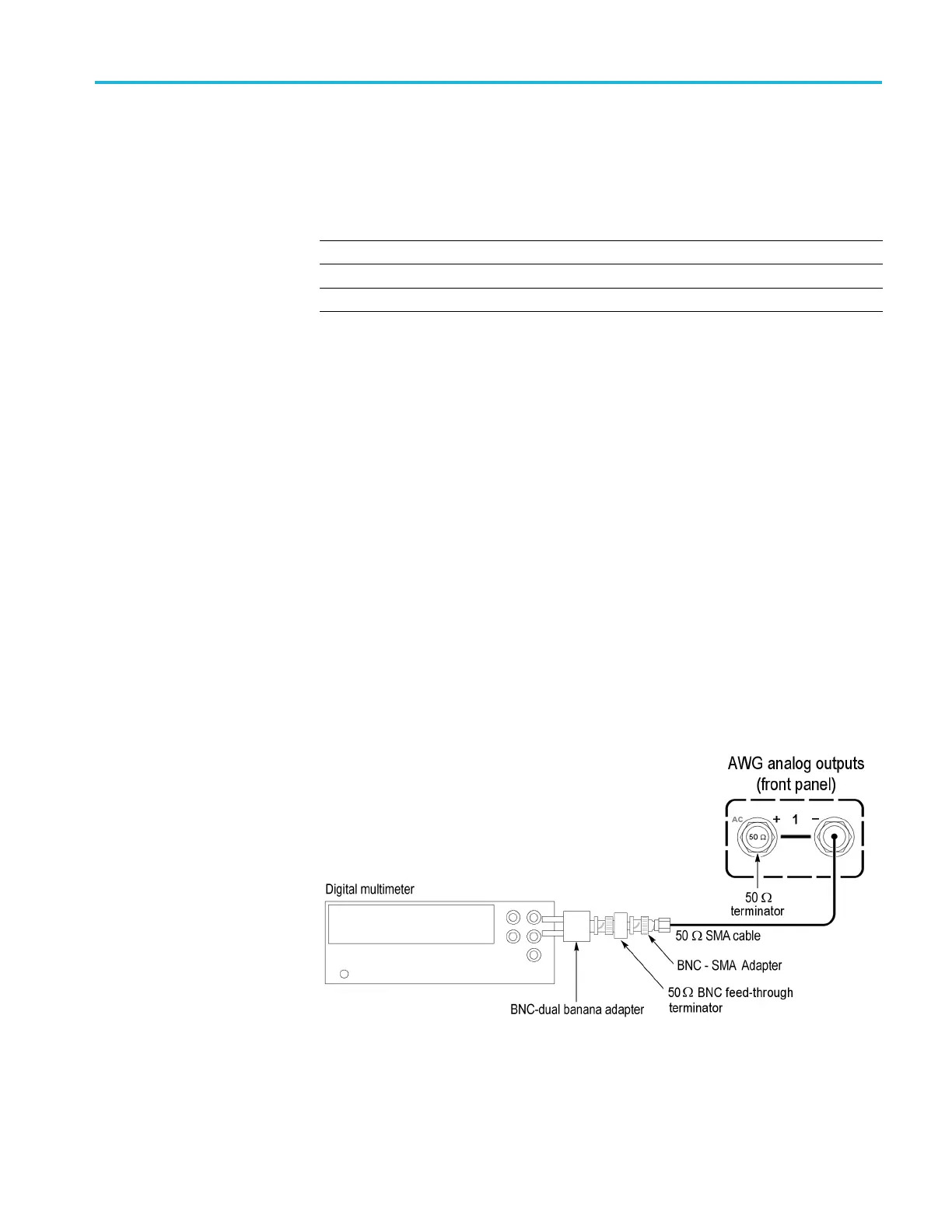
11. Measure the output voltage on the digital multimeter and note the value as
Measured_voltage.
12. Use the following formula to compensate the voltage for the 50 Ω BNC
feed-through terminator:
V = [(Term_R + 50) / (2×Term_R)] × Measured_voltage
Where Term_R is the resistance of the 50 Ω BNC feed-through terminator.
(See page 44, Termination resistance measurement.) procedure.
13. Verify that the voltage V falls within the limits given in the table. (See
Table 40 on page 53.)
14. Repeat steps 9 through 13 for each offset setting in the table. (See Table 40
on page 53.)
15. Press the AWG front panel All Outputs Off button (or click All Outputs Off
on the Home screen) to disable the outputs (front panel
light on).
16. Move the SMA cable from the CH 1 (+) connector to the CH 1 (–) connector
and move the 50 Ω SMA terminator from the CH 1 (–) connector to the CH
1(+)connector.
17. Press the AWG front panel All Outputs Off button (or click All Outputs Off
on the Home screen) to enable the outputs (front panel light off).
AWG5200 Series Technical Reference 53

 Loading...


