CFG253 Performance Verification & Adjustment Procedures
Page 5 of 19 Procedure #: CP1005 Revision: A
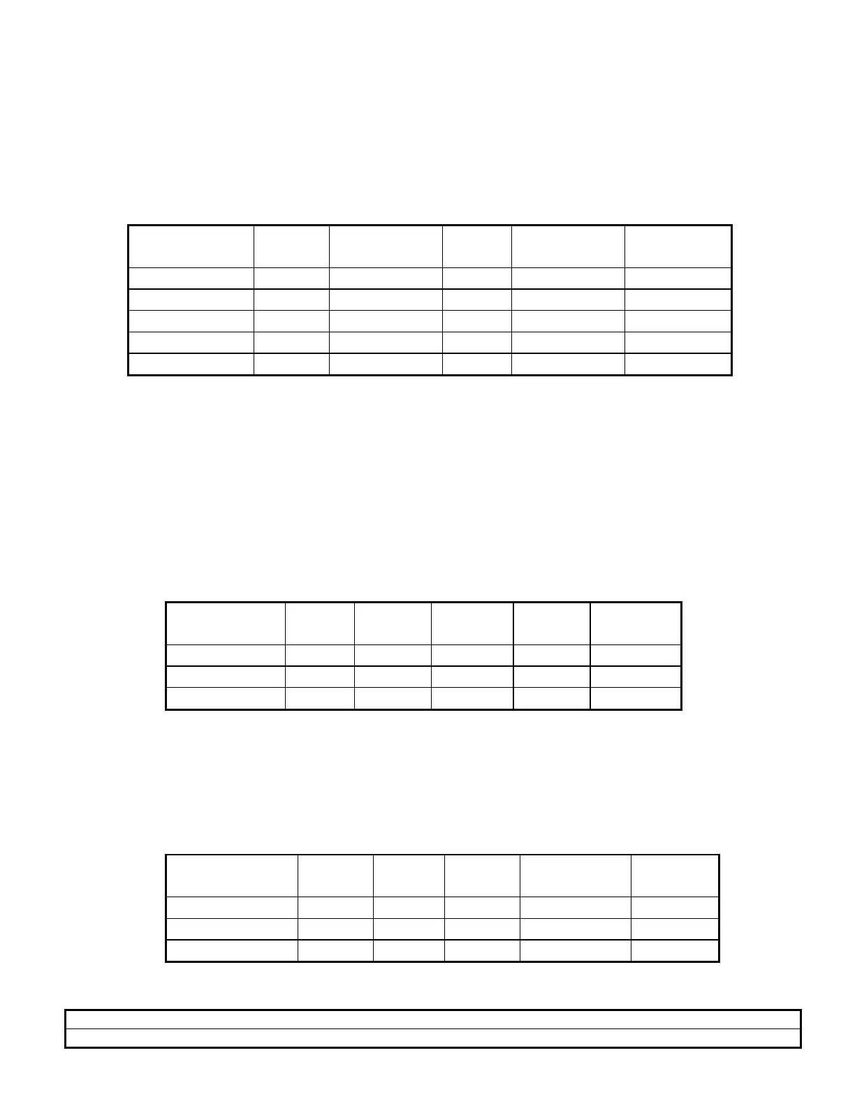
l. Set the FUNCTION to Square Wave. Use the CFG253 and test scope settings in
Table 1 to check the MAIN OUTPUT AMPLITUDE for the indicated settings :
TABLE 1
Function Range Volts Out
button
Freq.
Dial
Test Scope
Volts/Div
Test Scope
Display
Square Wave 1K Out 3.0 2V/Div > 5 Div
Sine Wave 1K Out 3.0 2V/Div > 5 Div
Sine Wave 1K Out 0.3 2V/Div > 5 Div
Square Wave 1K Out 0.3 2V/Div > 5 Div
Triangle 1K Out 0.3 2V/Div > 5 Div
m. Remove the 50 ohm terminator and connect the coax cable directly to the test
scope input.
n. Set the test scope Time/Div to 1uSec.
o. Check the test scope display for each setting in Table 2:
TABLE 2
Function Range Volts
Out
Freq.
Dial
Volts/D
iv
Display
Triangle 1M Out 3.0 5V/Div > 4 Div
SquareWave 1M Out 3.0 5V/Div > 4 Div
Sine Wave 1M Out 3.0 5V/Div > 4 Div
p. Press the VOLTS OUT button in. Check the test scope display for the settings in
Table 3:
TABLE 3
Function Range Volts
Out
Freq.
Dial
Volts/Div Display
Sine Wave 1M In 3.0 0.5V/Div > 4 Div
Square Wave 1M In 3.0 0.5V/Div > 4 Div
Triangle 1M In 3.0 0.5V/Div > 4 Div
 Loading...


