Reference Notes
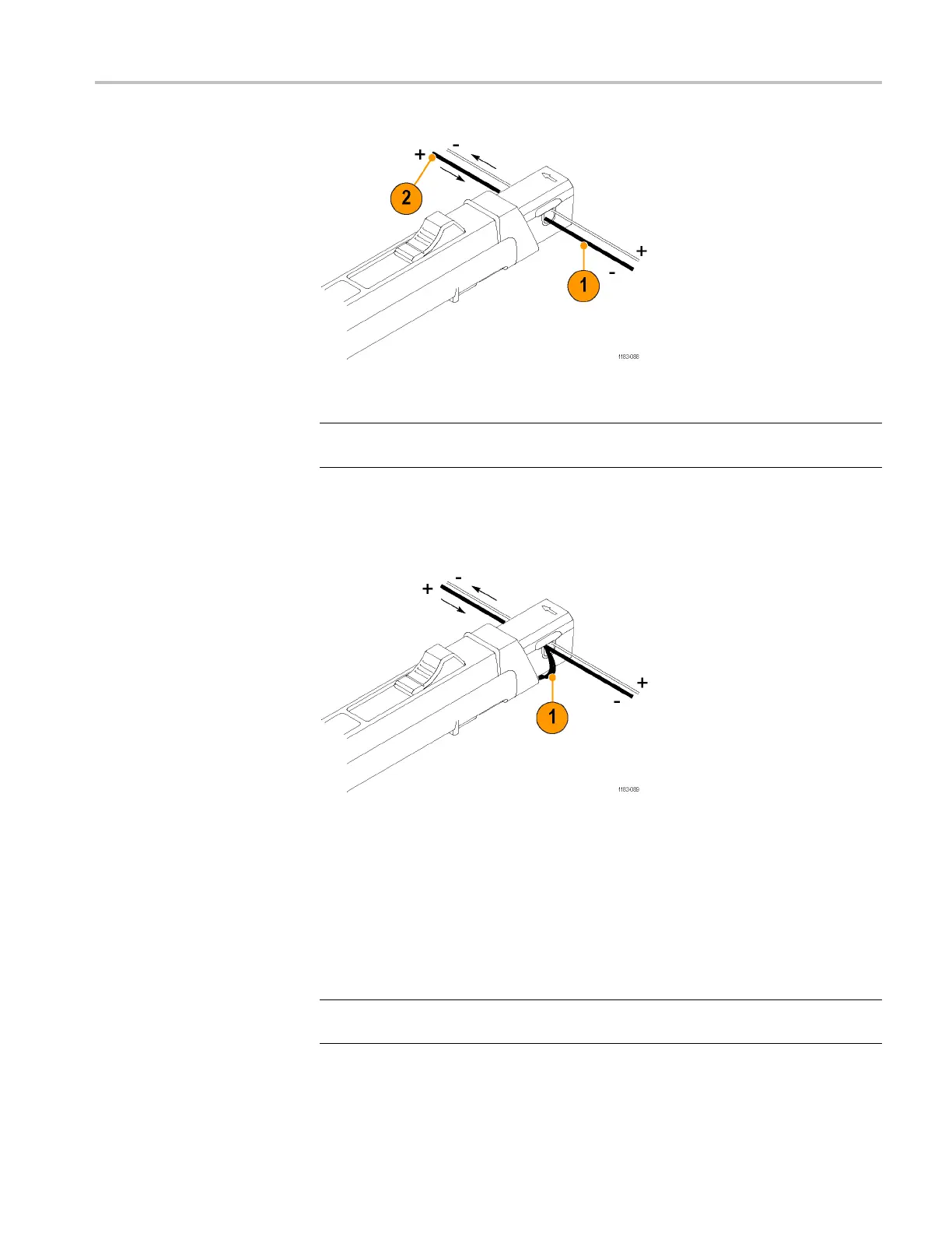
Figure 16: Adding a second conductor
NOTE. Adding a second conductor to the probe increases the insertion impedance
and reduces the upper bandwidth limit of the probe.
You can increase the value of the bucking current by winding multiple turns of the
second conductor around the probe, as shown in the illustration. (See Figure 17.)
Figure 17: Adding multiple turns
The bucking current is equal to the current fl owing in the conductor, multiplied
by the number of turns wound around the probe. For example, if the second
conductor has a current of 100 mA DC and is wrapped around the probe five
times, the DC bucking current is 100 mA multiplied by 5, or 500 mA DC.
To determine measurement values, add the value of the bucking current to the
displayed measurement.
NOTE. Winding multiple turns to the probe increases the insertion impedance and
reduces the upper bandwidth limit of the p robe.
TCPA300/400 Amplifiers and TCP300A/400 Series Current Probes User Manual 33

 Loading...

