Performance Tests
TDS 500D, TDS 600C, TDS 700D & TDS 714L Performance Verification and Specifications
1–99
Equipment
required
OIG501 (use with P6701B) (Item 26)
OIG502 (use with P6703B) (Item 27)
Optical Attenuator OA5022 (Item 34)
Fiber Optic Cable (Item 35)
Optical-to-Electrical Converter (item 36)
Prerequisites See page 1–17. Also, the probe and the oscilloscope channel it is
attached to must have been calibrated as a reference receiver.
1. Install the test hookup and preset the instrument controls:
Oscilloscope
Optical to electrical converter
Output
Input
Optical Impulse
Generator
Output
Optical
Attenuator
Fiber optic cable
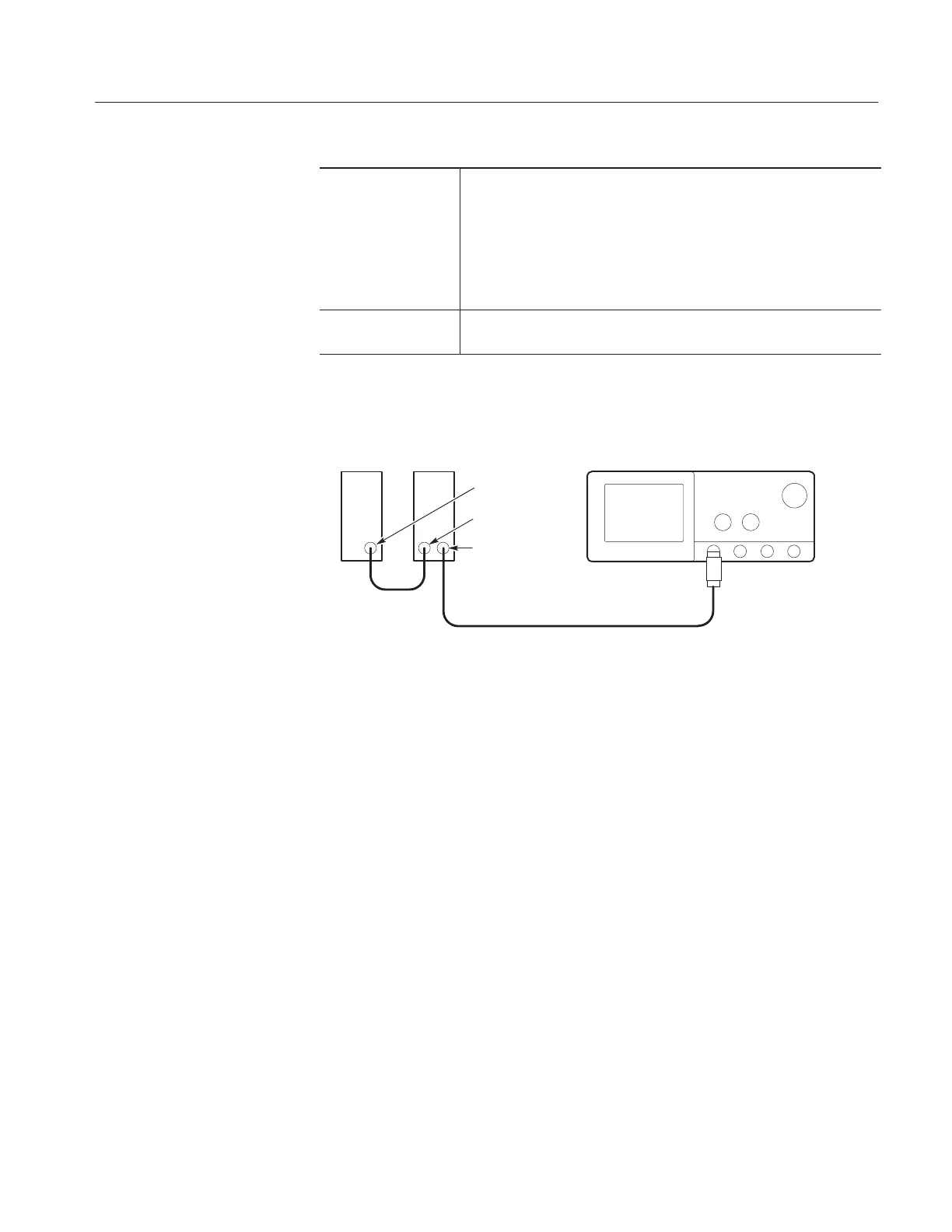
Figure 1–42: Reference-receiver performance-verification set up
a. Initialize the oscilloscope:
H Press SAVE/RECALL SETUP.
H Press the main-menu button Recall Factory Setup.
H Press the side-menu button OK Confirm Factory Init.
b. Connect the probe, oscilloscope, optical impulse generator (OIG), and
the optical attenuator:
H Connect the optical probe to CH 1 of the oscilloscope under test (see
Figure 1–42).
H See Table 1–10. If using a P6701B probe, connect the OIG501
(Item 26) OPTICAL OUTPUT to the optical attenuator (Item 34
)
OPTICAL INPUT using a fiber-optic cable (Item 35). If using a
P6703B probe, connect the OIG502 (Item 27) OPTICAL OUTPUT
to the optical attenuator (Item 34
) OPTICAL INPUT using a
fiber-optic cable (Item 35
).
Reference Receiver
Verification
Artisan Technology Group - Quality Instrumentation ... Guaranteed | (888) 88-SOURCE | www.artisantg.com

 Loading...


