pag. 3
CENTRATURA E COLLAUDO
Controllare che la tensione sia effettivamente quella impostata o
richiestadalmodelloealimentare.
A questo punto se l’allineamento della coppia non è
completamente sbagliato il ricevitore dovrebbe commutare
l’uscita.
Sequestononavvieneprocedereconlacentratura.
Per agevolare l’allineamento sia il Tx che l’Rx hanno il corpo
interno montato su molle e tramite due viti si può orientare in
orizzontale e in verticale (fig. 3) oltre a questo i ricevitori
dispongono di un led rosso: che si spegne quando la fotocellula è
centrata.
Siconsiglialacentraturaanchesesisenteilricevitorescattare.
Controllare il funzionamento interrompendo più volte il raggio
infrarosso, (il led rosso sulla ricevente deve accendersi ed il relè
scambiare). Questa operazione deve essere ripetuta anche
dopoaverposizionatoilcoperchiodell’RXedel’TX.
Il filtro centratura (fig. 4) serve per un ulteriore test e per essere
sicuri che anche in condizioni peggiori esempio nebbia o pioggia
tuttofunzioni.
Il test è semplice e veloce, basta appoggiare la pellicola su uno
dei frontalini (fig. 5) e controllare che la fotocellula funzioni
correttamente; se non funziona, o siamo al limite della portata o
l’allineamentononèperfetto.
Attenzione ricordarsi di togliere la pellicola al termine delle
prove.
CENTRING AND TESTING
Check that voltage is the same as that set or required for the
modelandswitchpoweron.
At this point, if alignment of the pair is not completely wrong, the
receiver should switch the output. If this does not happen
proceedwithcentring.
To facilitate alignment, the inside bodies of both the transmitter
and receiver are mounted on springs and, with two screws, they
can be swivelled horizontally or vertically (Figs. 3). Besides this,
the receivers are fitted with a red LED that switches off when the
photocelliscentred.
Werecommend centring even if you hear the receiver click.
Check functioning by passing in front of the infrared ray several
times (the red LED on the receiver should turn on and the relay
should switch). Repeat this also after the covers of the receiver
andtransmitterhavebeenpositioned.
The centring filter (Fig. 4) is used for an additional test and to be
sure that even in the worst conditions, like fog or rain, everything
worksproperly.
The test is quick and simple: place the film on one of the fronts
(Fig. 5) and check that the photocell is working properly. If it does
not it means we are either at the limit of its range or alignment is
notaccurate.
Attention: remember to remove the plastic film when you
havefinishedtesting.
CENTRAGE ET ESSAI
Contrôler que la tension correspond à celle qui est effectivement
sélectionnéeoudemandéeparlemodèleàalimenter.
À ce point, si l'alignement du couple n'est pas complètement
erroné, le récepteur devrait commuter la sortie. Si ça n'est pas le
cas,procéderaucentrage.
Pour faciliter l'alignement, aussi bien le TX que le RX ont le corps
interne monté sur des ressorts et il est possible de l'orienter
verticalement ou horizontalement en agissant sur les vis (fig. 3);
les récepteurs disposent en outre d'une diode
électroluminescente rouge lequel s’éteint avec la précision du
centrage.
Il est conseillé de procéder au centrage même si l'on entend
l'interventiondurécepteur.
Contrôler le fonctionnement en interrompant plusieurs fois le
rayon infrarouge (la DEL rouge sur le récepteur s’allume et le
relais doit commuter). Cette opération doit être répétée
égalementaprèsavoirmislecouvercleduRXetduTX.
Le filtre de centrage (fig. 4) sert à un test supplémentaire et pour
être sûrs que tout fonctionne même dans les pires conditions
commeparexempleencasdebrouillardoudepluie.
Le test est simple et rapide, il suffit de poser la pellicule sur l'une
des façades (fig. 5) et de contrôler que la photocellule fonctionne
correctement; si elle ne fonctionnepas, cela signifie que l'on est à
lalimitedelaportéeouquel'alignementn'estpasparfait.
Attention, ne pas oublier d'enlever la pellicule à la fin de
l'essai.
NO
NC
C
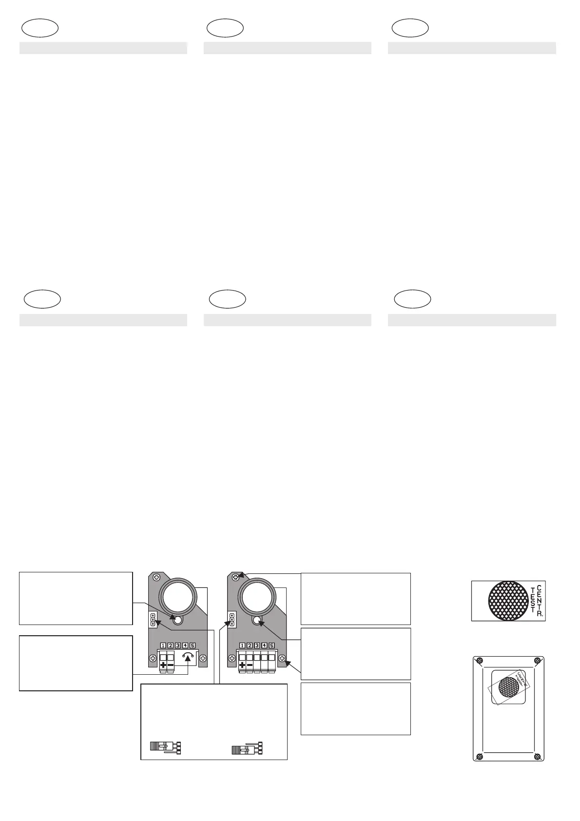
CAMBIO TENSIONE CON PONTE (JUMP)
CHANGEMENT DE TENSION AVEC PONTET (JUMP)
VOLTAGE CHANGE WITH JUMPER
SPANNUNGSWECHSEL MIT BRÜCKE (JUMP)
CAMBIO TENSIÓN CON PUENTE (JUMP)
KEUZE VOEDINGSSPANNING BRUGJE (JUMPER)
REGOLAZIONE VERTICALE
VERTICAL ADJUSTMENT
RÉGLAGE VERTICAL
VERTIKALE EINSTELLUNG
REGULACIÓN VERTICAL
VERTICALE REGELING
12V
LED VERDE ALIMENTAZIONE
GREEN POWER ON LED
LED VERT ALIMENTATION
LED VERDE
GRÜNE VERSORGUNGS-LED
ALIMENTACIÓN
GROENE LED VOEDING
LED ROSSO CENTRATURA
REDCENTRINGLED
LED ROUGE CENTRAGE
ROTEZENTRIER-LED
LEDROJOCENTRADO
RODELEDVOOR UITLIJNING
24V
REGOLAZIONE ORIZZONTALE
HORIZONTAL
HORIZONTAL ADJUSTMENT
RÉGLAGE
HORIZONTALE EINSTELLUNG
REGULACIÓN HORIZONTAL
HORIZONTALE REGELING
Fig. 3
TAGLIARE PER SINCRONISMO
CUT FOR SYNCHRONISM
COUPER POUR SYNCHRONISME
FÜR SYNCHRO-SYSTEM DURCHSCHNEIDEN
CORTAR PARA SINCRONISMO
KNIPPEN VOOR SYNCHRONISATIE
TX
RX
I
F
UK
O
D
U
A
L
L
O
C
L
I
O
P
O
D
E
R
E
I
L
G
O
T
Fig. 4
O
D
U
A
L
L
O
C
L
I
O
P
O
D
E
R
E
I
L
G
O
T
Fig. 5
D
NL
ES
ZENTRIEREN UND ENDPRÜFUNG
Prüfen, ob die Spannung effektiv die eingestellte oder die vom
Modellgeforderteist und Spannung geben.
Nun müsste, wenn die Fluchtung des Fotozellenpaars nicht ganz
falschist,der Empfänger denAusgang umschalten.
Solltediesnicht erfolgen, muss zentriert werden.
Für eine leichtere Fluchtung ist der Innencorpus des Senders und
des Empfängers auf Federn montiert und kann durch zwei
Schrauben horizontal und vertikal verstellt werden (Abb. 3); darüber
hinaus verfügen die Empfänger über eine rote LED, die erlischt,
wenndieFotozelle zentriert ist.
Das Zentrieren wird auch, wenn man hört, dass der Empfänger
ausgelöstwird,empfohlen.
Den Betrieb kontrollieren, indem der Infrarotstrahl mehrmals
unterbrochen wird (die rote LED am Empfänger muss aufleuchten
und das Relais umschalten). Dieser Vorgang muss nach dem
AnbringendesDeckels auf RX undTX wiederholt werden.
Der Zentrierfilter (Abb. 4) dient zu einem weiteren Test und um
sicher zu sein, dass alles auch bei schlechtesten Bedingungen wie
zumBeispielNebel oder Regen funktioniert.
Der Test ist einfach und schnell. Es genügt, die Folie auf eines der
Frontteile (Abb. 5) zu legen und zu kontrollieren, ob die Fotozelle
korrekt funktioniert; falls nicht, sind wir an der Grenze der Reichweite
oderdieFluchtung ist nicht bestens.
Achtung:dieFolie am Ende der Testswieder entfernen.
4
CENTRADO Y ENSAYO
Controle que la tensión sea efectivamente aquella configurada o
exigidaporel modelo y conecte.
Ahora, si la alineación del par no es completamente incorrecta el
receptor
deberíaconmutarla salida.
Siasíno fuera, centre las fotocélulas.
Para facilitar la alineación tanto el Tx como el Rx tienen el cuerpo
interno montado sobre muelles y con dos tornillos puede orientarse
horizontal y verticalmente (fig. 3), además estos receptores cuentan
conunled rojo que se apagacuandola fotocélula está centrada.
Se aconseja efectuar el centrado aunque se oye que el receptor se
dispara.
Controle el funcionamiento interrumpiendo varias veces el rayo
infrarrojo (el led rojo en el receptor debe encenderse y el relé
conmutar). Dicha operación se tiene que repetir también después de
habercolocadola tapa del RX ydelTX.
El filtro de centrado (fig. 4) sirve para un test posterior y para estar
seguros de que todo funcione aún en las peores condiciones, por
ejemploconniebla o lluvia.
El test es sencillo y rápido, basta apoyar la película sobre uno de los
frentes (fig. 5) y controlar que la fotocélula funcione correctamente;
de no funcionar significa que estamos al límite del alcance o que la
alineaciónnoes perfecta.
Atención:recuerde quitarlapelícula al concluir los ensayos.
4
UITLIJNEN EN TESTEN
Belangrijk: vergeet niet het filter te verwijderen uitvoeren van
detest.
Controleerdevoedingsspanning en schakel ze aan.
Als de uitlijning vrij juist is zal nu de uitgang van de ontvanger
schakelen. Indien dit niet is moeten de ontvanger en/of zender
uitgelijndworden.
Om de fotocellen uit te lijnen zijn er in de behuizing twee
stelschroeven met veren voorzien voor de horizontale en verticale
uitlijning(fig.3).
Tevens is de ontvanger voorzien van een rode LED die dooft als de
fotocellencorrectuitgelijnd zijn.
Het is noodzakelijk dat, zelfs indien het relais klikt, de uitlijning
gecontroleerdwordt.
Controleer de werking van de fotocellen meerdere keren door de
infrarood straal te onderbreken (de rode LED op de ontvanger moet
doven en het relais schakelt). Herhaal deze test nadat u het deksel
vandezender en de ontvanger gemonteerdhebt.
Het centring filter (Fig. 4) wordt gebruikt voor een bijkomende test om
er zeker van te zijn dat de fotocellen ook goed werken bij regen en
mist.
Deze test is vrij eenvoudig: kleef het filter op de zender of op de
ontvanger (Fig. 5) en controleer de werking van de fotocel. Indien de
fotocel niet correct functioneert is de uitlijning fout of de afstand
tussenzenderen ontvanger te groot.
4
 Loading...