DEMOLITION
You have to operate the elimination of the materials in conformity with
the regulations in force. All materials must be divided by type (copper,
aluminium, plastic, electrical parts, etc)
DISMANTLING
In order to move away the automation, follow these instructions:
1 - cut off the power supply and disconnect the electrical installation;
2 - dismantle the control console and all the other components of the
installation.
If you have noticed that some components have been damaged, you
have to replace them.
CONFORMITY DECLARATION:
It’s in accordance with Machine Directive 39/89/CE and following
modify.
It’s in accordance with the following directive CE:
Electromagnetic compatibility Directive 89/336/CEE and following
modify.
Low tension Directive 73/23/CEE and following modify.
Have been applied the following harmonized norms:
EN292/1/2, EN 294, EN60335-1, UNI EN 12453, and what applicable
of the EN12445-2000.
USE OF THE AUTOMATION
The gearmotor STONE 300-400-600 GR was designed and built for
the opening of gates with max of 5 m leaf or weight max. 200kg. The
CARDIN ELETTRONICA Spa assumes no responsibility for a purpose
other than that provided by gearmotor STONE 300-400-600 GR. Since
automation can be put into motion in view by button or remotely by
remote control, it is essential to check frequently the perfect efficiency
of all safety devices. It is advisable to check periodically (every six
months) the regulation of electronic friction of which must be equipped
the electronic control board.
PRELIMINARY CHECKS
1 - Read carefully the instructions enclosed in this manual.
2 - Make sure that the gate has a rather solid structure and that there
is no friction points in its movement.
3 - Make sure that the leaf is suitably balanced, even after the
installation of the gear motor.
4 - Check that the electrical installation is in accordance with the
characteristic required by the gear motor.
TECHINICAL DATA
SCHEDULED MAINTENANCE
Control of gate hinges and supports, balancing of the
gate
Check the status of welds and corrosion.
Unhook the engine and check the
balancing and the eventual points of
friction.
Controlling the sensitivity of electronic friction (torque
adjustment) of the control board.
Check the adjustment of the couple as
described in EN 12453 - EN 12445
Monitoring current dispersion
Verify that the dispersion of current is
less than 7.5 A
Verify that the safety warning signage is
complete and intact
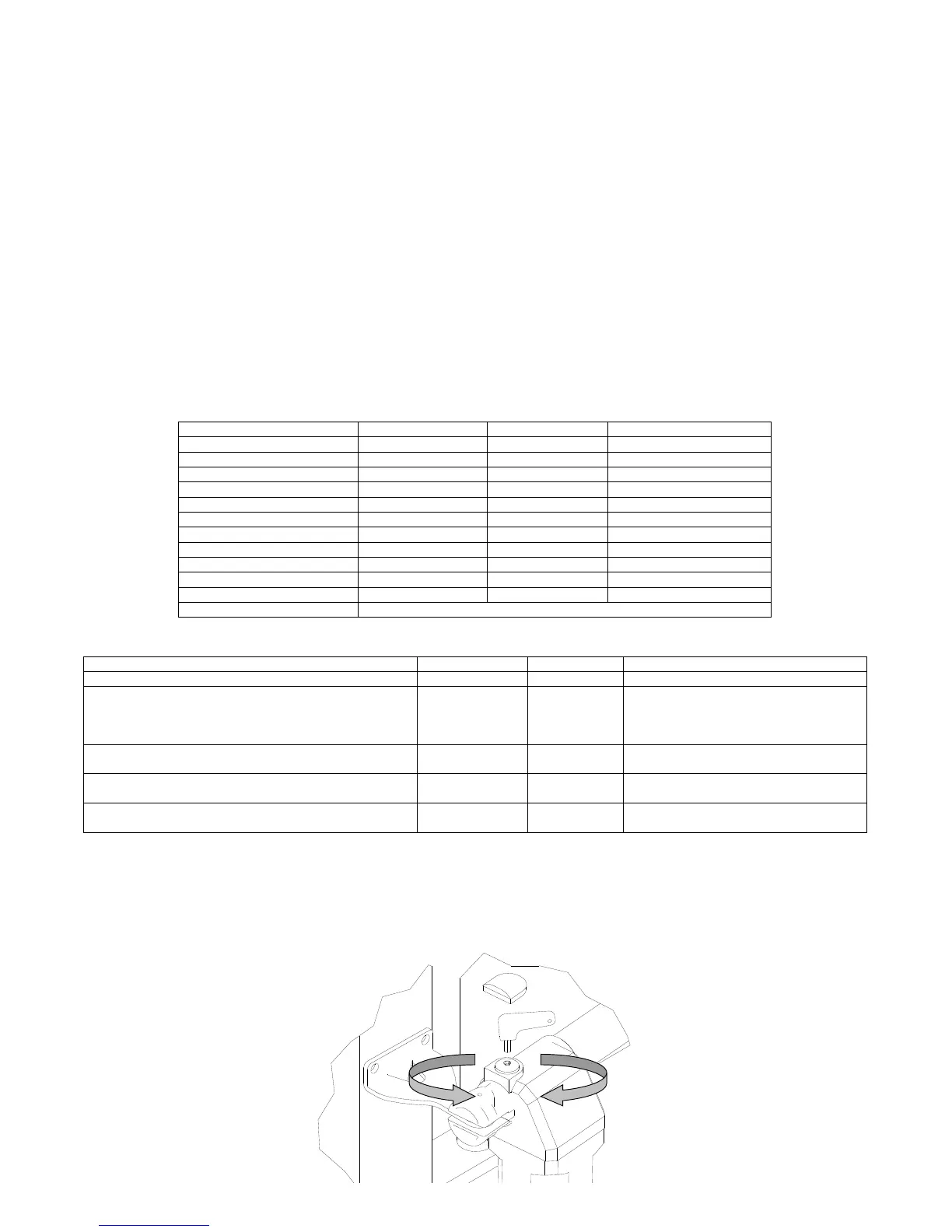
EMERGENCY MANOEUVRE
For the manual door locking and unlocking act with the supplied key on the screw C (See FIG 1-2).
1 - Remove the protection cap
2 - insert the key into the seat allocation as in Figure 1
3 - Turn the key in the sense of the arrow to the top of the gearmotor to unlock and in the opposite block.
Maximum length of the gate
Maximum weight of the gate
 Loading...